Stuck?  support@mecway.com
support@mecway.com
Mecway
FEA
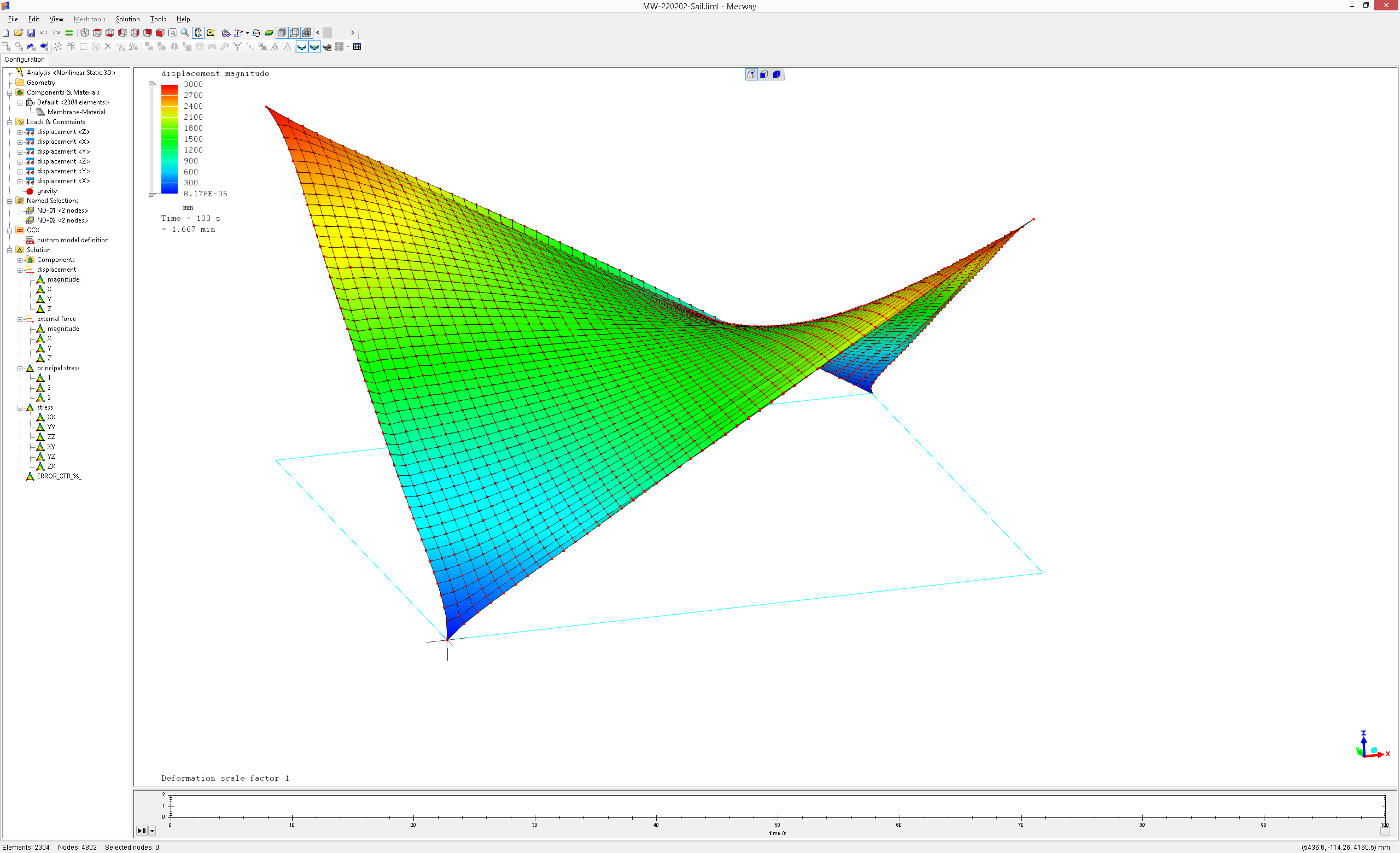
Form-finding on tensile structures.

Good evening COMMUNITY and VICTOR:
I enclose you a form-finding prototype on tensile structures. I modelled a square on the floor and lifted 2 corner nodes 3 meters up. To do that I used boundary conditions(displacements). I hope you enjoy the resulting 3D shape. It turned out to be a hyperbolic paraboloid. Regarding the fabric/woven material, I used TENSION_ONLY material, visit "custom model definition" on the general tree. To achieve the final shape quasi-static non linear 3D analysis on MECWAY v14th CCX 2.19 in-built needs to be performed.
Best regards
MANUEL MARTÍN
Howdy, Stranger!
It looks like you're new here. If you want to get involved, click one of these buttons!
Comments
¿May I ask you something?
I have notice there are some additional materials properties defined in the custom model definition.
I have read in the ccx manual about them to understand their meaning and
0.0005 (refers to thickness of the shell in meters)
• Enter the CONSTANTS parameter and its value. The value of this parameter is 2.
Following line:
• E.
• absolute value of the maximum allowed pressure.
• Temperature.
15E9, Young Modulus.
5E6, absolute value of the maximum allowed pressure.
N/A Temperature.
What does “Absolute value of the maximum allowed pressure” means? Is it the Yield Strength?
¿Which values prevail when there is a custom model definition, E=15E9 or the values defined in MECWAY?
The TENSION_ONLY material only can be declared in "the custom model definition" item because MW does not yet support this material straightforward.
-Regarding 0.0005(in meters according to VICTOR'S directions)=0.5mm. This is the thickness of the fabric used on shell elements.
You are right about the constant definition. By the way, I did not include temperature definition.
Only one thing to point out, the maximum allowed compression needs to be written down in |absolute value(N/m=Pa)|, otherwise it won't work out.
In case you are interested in TENSILE_ONLY/COMPRESSION_ONLY materials, I recommend you to visit my recent post about "Clay arch simulation" in which I use a COMPRESSION_ONLY material assigned to tetrahedron elements. This kind of material model is required to perform brittle material simulations such us concrete, masonry or clay. I hope, maybe some day, that CALCULIX will code "smeared cracking materials" for simulating brittle materials however, right now, it is fine for me.
Thank you very much for your comments. I really appreciate it.
MANUEL
Thank’s for your response. I’m not sure 100% of which properties prevail when defining a custom model. Check carefully because the “Mass” tool use the density from MECWAY not custom model.
If some values in the Solution Tree are computed internally using density, the result may be wrong. Don’t know about the others E, Poisson,…
@disla. Good point that the mass tool in the solution ignores any density defined in the CCX branch. Formula field variables depending on mass would have that problem too. But I think all the built-in field variables like stress, displacement, etc. use only the solution data from CCX, and at most transform it, such as converting stress components to principal stress, so that should all be fine.
About the wrinkle on the edge:
I agree with you, the wrinkle on the edge is nice and MW caught that behaviour perfectly.
In real like, that wrinkle needs to be removed.
To do that, I must must cut off fabric on the edge(modifying the 3d model) and add a perimetral pre-stressed steel cable. I must design a 100% tension fabric (0% compression).
MANUEL
Perimetral steel it's being crucial to keep some initial tension and make it converge.
Wrinkles may develop at the lower edges too.
Runs in about 5 min with Pastix.
ccx 2.19 is required.
Thanks for your inspiring example Manuel.
Disla pointed me this thread some time ago to share some directions to simulate sails. I played with the proposed examples and it is encouraging. But this definitively looks like not trivial FEA use cases, often on the verge of convergence issues.
I recognize that I lack practical and theoritical experience in FEM. And I'm trying to use it as a tool, as a hobby, to better understand some mecanism in my sailing practice.
I don't succeed in grasping the relation between the model convergence issues and the physics or models limitations behind. What are the configurations, or the results that indcate difficult areas of the simulation that need attention? Why does this configuration converge, and that one not? So I find myself playing with parameters with trials and errors to identify a domain where the model converge (forces, thickness, mechanical properties...).
If I was able to understand better what is to be looked at in the model and simulation results to indicate convergence difficulties, that would help me to improve the model, or have more success in parameters tuning.
If someone can share some understanding on this topic, I would be very grateful :-)
Best regards,
JMF
Hard problem and not too much information on the net. I have never built or design a Sail, that is the first to say and I assume it can be a very deep subject as it involves FSI. I have found you asking a similar question on other forums and mostly related with windsurfing sails as reference.
I know these kinds of sails well as I windsurf since I was a child but never thought about them from an engineering point of view. As a very simple beginning , I would start looking at them as a simple buckling problem.
¿Have you noticed that good sails get almost their final shape just after the mast assembly? 90% of the sail shape is mostly recognized once you assembly the mast. (Talking about windsurf sails).
I would start looking at the first buckling mode of different masts profiles. Masts with different thickness patterns (thickness of the section and thickness variation with hight).
That would help me to :
-Adjust the mast curve to the luff curve . The curve will move up or down depending on the thickness profile and material stiffness.
-Get the tension required to start the mast bending (Buckling)
-Get some qualitative shapes.
-Get an idea of required thickness and resulting weight.
-Will help you to discard some options and focus on a design line.
Try to start with some SDM standard mast or one you like as starting point and then make small changes to see their effect .
I think this could be an affordable first step if you do not have too much experience with fea. Buckling analysis of a mast should be from the computational point of view, fast, not too difficult to set up, easy to make it work, not convergence issues and easy to make changes and experiment different shapes.
Forget about the sail itself by the moment. I'm sure you can get results in a few days that will increase your enthusiasm and will help you to further progress.
I would use it to calibrate/validate my profile. Try to reproduce fabricator IMCS. FEA model can give you all the numbers to compute IMCS.
Note IMCS is computed from a bending test not Compression test (Buckling). I can imagine it is much easier to set this test in a workshop.
https://unifiber.net/windsurf-masts/bend-curves
https://www.unifiber.net/windsurf-masts/mast-measurement
As I comment , I would focus first on the mast.
Edited. Added a liml file as example on how I would set up the mast. See how the shape change (qualitative) just with one mm. Keep in mind Buckling deformation shape (quantitative) is scaled and not real. To get the real shape you need to go to Nonlinear. (later)
I guess you need a good modeled mast to further use it to introduce some realistic loads on the sail.
Thanks a lot for taking the time to answer. I agree with all your points. I already played with the mast simulation to have the "skeleton" OK.
The issue is with the sail. And this is clearly my point here. If I don't understand the way to model, the limiting parameters for convergence, how to diagnose the model to find the way forward... then I will stop and "just sail".
I have read several academic papers, which says that for such simulations it has to be paid attention to convergence, without giving much details. There are obviously different ways to model the sailcloth, either with CST, or shells. Here is another exemple with TENSION_ONLY materials. It is embedded in commercial products. This is engineering now, not science anymore
But many of my simulations don't converge anymore when I extend a bit the tensions/displacements/elasticity... And I don't identify the area of concern, the diagnosis, which would help set an action plan to extend successfully the simulation domain :-(
This is not so important, as it is an hobby... But I would be happy to have a tool to assess qualitatively the effect of some parameters as battens stiffness, luff curves modification and so on, on the sail shape under load (FSI).
Best regards,
JMF
".... I would be happy to have a tool to assess qualitatively the effect of some parameters as battens stiffness, luff curves modification and so on, on the sail shape under load (FSI)"
Woow..
Check the Golden rules (page 16 ccx v2.19 manual).
I will re-read the calculix golden rules. Do you have one especially in mind ?
Windsurfer sails are pretty optimized now, But some experts worked on models and simulation to optimize the Windfoil race sails.
My application scope are landyacht sails. This is really a niche domain with few specificities, which has been I believe much less optimized than some other sailing areas.
JMF
Mainly the first two.
Check the quality of your mesh and if you are experiencing convergence problems , solve the linearized model first (linear elasticity, isotropic material..)
Try to understand how the different parts interact solving the 2D problem first if possible.
They all belong to a more general rule that would say: Increase complexity step by step.
That's why I said to work first on the mast.
Mast example: Euler buckling load of a hallow tube (Initial vertical tensile load transferred to the luff)
F = n * π^2 * E * I/ L^2
You can easy double the tensile on the luff and ruin the convergence playing with E or moving from 1mm to 2 mm thickness.
A simple blunt way to protect against all those problems by supporting everything with weak springs. You could use Elastic support or cover it with a layer of low stiffness material and fixed support.
You may also get some insight by using the LAST ITERATIONS option in the *NODE FILE card. I haven't used this myself but it's supposed to show the results of iterations leading up to the failure so you might see part of it oscillating wildly or something.
In the simple cases I tried to work on, I had the feeling that I was not in above cases:
- constraining all the corners of a flat surface modelled by shell elements
- applying a uniform pressure on it, which in real world should build tension in the surface that opposes to the pressure,
- with above, I don't see compression building in the surface or buckling conditions.
I will try to play with LAST ITERATIONS option, and explore the workarounds to propose.
Maybe it is also me using the Mecway demonstration version and not using enough nodes to model my use case...
Let's explore a bit more that topic with simple examples.
JMF
That sounds like a problem since the first iteration will have the applied pressure but none of the tension caused by that will have appeared yet, so the entire pressure is resisted only by bending stiffness of the material which I guess is very low. I would ramp up the pressure gently, so that initially, it's low enough for the material's bending stiffness.