Stuck?  support@mecway.com
support@mecway.com
Mecway
FEA
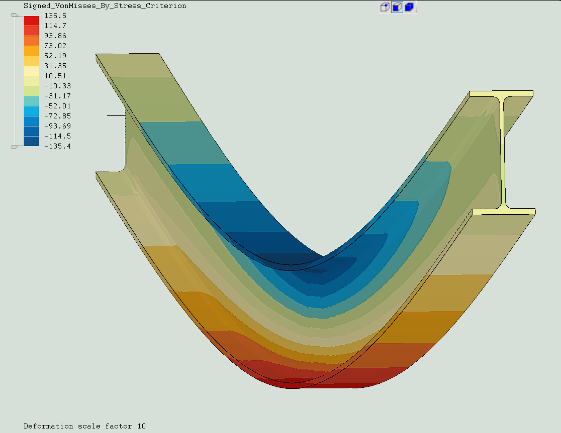
Beams from shell expanded with variable node thickness.

Hi,
I think this is a new approach in the forum to the way of modeling beams. At least I haven't seen it before.
It is not easy to set up, but the final stress distribution is very gentle and detailed without peaks and it’s not as heavy as a solid beam. It can accommodate many non-standard beam sections including their flange radii.
Agreement with theory is very good.
Maximum displacement.
Theory: 24.66 mm
Result : 24.87 mm
Rotation.
Theory: 0.70642 º
Result ROTX = 0.70642 º
Will surely surprise some of you and may open to other ideas.")
Regards
I think this is a new approach in the forum to the way of modeling beams. At least I haven't seen it before.
It is not easy to set up, but the final stress distribution is very gentle and detailed without peaks and it’s not as heavy as a solid beam. It can accommodate many non-standard beam sections including their flange radii.
Agreement with theory is very good.
Maximum displacement.
Theory: 24.66 mm
Result : 24.87 mm
Rotation.
Theory: 0.70642 º
Result ROTX = 0.70642 º
Will surely surprise some of you and may open to other ideas.
Regards
Howdy, Stranger!
It looks like you're new here. If you want to get involved, click one of these buttons!
Comments
¿Do you see too much inconvenience in writing the shell thickness adding the *NODAL THICKNESS card?
That would mean moving from :
*SHELL SECTION,ELSET=SHELL1,MATERIAL=MAT1,OFFSET=0
0.005
To here:
*SHELL SECTION,ELSET=SHELL1,MATERIAL=MAT1,OFFSET=0,NODAL THICKNESS
0.005
*NODAL THICKNESS
N-SHELL1,0.005
It seems the same but last would allow to introduce custom thickness corrections to a given set of nodes on the shells which could translate for example in the possibility of defining the weld root thickness and shape.
See Attached example.
Add *NODAL THICKNESS to the Modify Keyword option window so it could be change there acting just on a named Node Set.
Replying to first post. Very clever.
Curious to find an efficient way you constructed it (?). I observed it was MUCH easier starting with Line3 elements up one end, then extrude into (one) column of stacked quad8 elements, then set up the Named Ranges before copying all the whole length of the beam (which then auto-updates the Ranges). I tried it another way, but I was having fits scrolling in/out trying to pick clean the nodal rows (Teams).
Since CCX is expanding the shells into solids, I think the solution is also reflecting the shear deflection present in the beam (+0.25mm), when added to your beam deflection further confirms your approach. I was additionally able to duplicate your numbers with an extruded automeshed model (60k node).
The shear deflection component truly bears greater influence the shorter the beam gets (but a lot of guys ignore it in hand calculations.) Tested a shorter 1000mm length beam under same loading (theory 0.114mm bend. + 0.042mm shear = 0.156mm tot.), compared with CCX results of 0.149mm measured at bottom.
For the weld idea: Seems your method can produce any number of full-width slices. Looking at the recently posted Hot-Spot method, do I need more resolution laterally (normal) to the weld?
Nice work. Thanks for the examples.
~CW
Right. Nice point.
Theory: 24.66 mm + 0.24mm= 24.9mm
Result : 24.87 mm
Deviation : 0.1%
To build the section I have start from my standard section library. It was published in the forum some years ago.
https://mecway.com/forum/discussion/1001/library-of-steel-beam-sections-according-to-en
This is my workflow. Let me know if you have any doubt.
EDITED: Notice for thickness to be twice the X coordinate of the node beam must be centered at x=0.