Stuck?  support@mecway.com
support@mecway.com
Mecway
FEA
Rayleigh Damping Coefficients

HI,
I have set up a file that can help to understand how Raileigh Damping works with Dynamic, how to find the coefficients and what do they physically mean.
The file has a set of 100 springs/mass with increasing first vibrating mode according to the attached file Rayleigh-damping-Springs Material Data.pdf
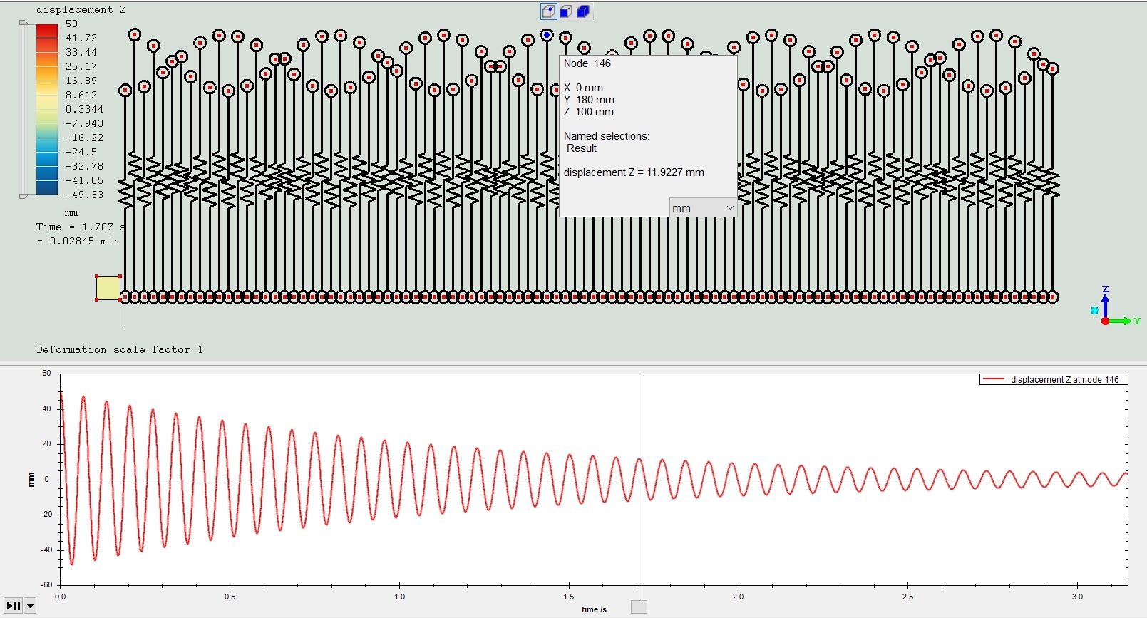
The key point is that all of them have the same initial imposed displacement, so they all vibrate naturally at its own frequency but all with the same initial amplitude. That allows to detect differences in amplitude and how Raileigh Damping affects each frequency.
The pdf shows how to adjust alfa and beta to obtain the desired response.
Basically, in ccx you can provide three types of damping.
Damping proportional to the stiffness
Damping proportional to the inertia
And a mixture of both.
The easiest and more intuitive way I have found to proceed is the following:
1-Decide the desired amplitude decay. That means how much in % will the amplitude decay in one cycle. (Typical values in structural design are 2% and 5%)
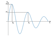
2-Compute X0/X1
3-Compute Logarithmic Decay delta
4- Compute damping ratio zeta. Value needed later in the different options.
Option 1- Damping proportional to the stiffness (Alpha=0)
From the set of natural angular frequencies of your system select one w1 that will have the desired amplitude decay stablished in point 1. (2%, 5%,…) . As damping is proportional to Stiffness in this model, that pair of points (w1 , zeta) will define and determine all the other damping ratios of all the natural frequencies that the system may have. The larger the w, the larger the damping. See graph. Is linear. All high frequencies will be cut very fast. Low frequencies will survive longer.
Option 2- Damping proportional to the inertia (Beta=0)
Same idea but now high frequencies will survive. You now need to decide which angular frequency w1 will determine the frontier between growing damping values and decreasing damping values. See Graph.
Option 3- A mixture of both.
Can you imagine?. Right. Extreme angular frequencies are removed and central frequencies between two selected (w1 and w2) survive more time. See Graph.
Formulas will help you to find the right coefficients to obtain your desired damping behavior and Amplitude decay per cycle.
Please comment if you see any mistake.
I have set up a file that can help to understand how Raileigh Damping works with Dynamic, how to find the coefficients and what do they physically mean.
The file has a set of 100 springs/mass with increasing first vibrating mode according to the attached file Rayleigh-damping-Springs Material Data.pdf
The key point is that all of them have the same initial imposed displacement, so they all vibrate naturally at its own frequency but all with the same initial amplitude. That allows to detect differences in amplitude and how Raileigh Damping affects each frequency.
The pdf shows how to adjust alfa and beta to obtain the desired response.
Basically, in ccx you can provide three types of damping.
Damping proportional to the stiffness
Damping proportional to the inertia
And a mixture of both.
The easiest and more intuitive way I have found to proceed is the following:
1-Decide the desired amplitude decay. That means how much in % will the amplitude decay in one cycle. (Typical values in structural design are 2% and 5%)
2-Compute X0/X1
3-Compute Logarithmic Decay delta
4- Compute damping ratio zeta. Value needed later in the different options.
Option 1- Damping proportional to the stiffness (Alpha=0)
From the set of natural angular frequencies of your system select one w1 that will have the desired amplitude decay stablished in point 1. (2%, 5%,…) . As damping is proportional to Stiffness in this model, that pair of points (w1 , zeta) will define and determine all the other damping ratios of all the natural frequencies that the system may have. The larger the w, the larger the damping. See graph. Is linear. All high frequencies will be cut very fast. Low frequencies will survive longer.
Option 2- Damping proportional to the inertia (Beta=0)
Same idea but now high frequencies will survive. You now need to decide which angular frequency w1 will determine the frontier between growing damping values and decreasing damping values. See Graph.
Option 3- A mixture of both.
Can you imagine?. Right. Extreme angular frequencies are removed and central frequencies between two selected (w1 and w2) survive more time. See Graph.
Formulas will help you to find the right coefficients to obtain your desired damping behavior and Amplitude decay per cycle.
Please comment if you see any mistake.
Howdy, Stranger!
It looks like you're new here. If you want to get involved, click one of these buttons!
Comments
I have first identified the dominant mode w1. (7.14 Rad/sec)
As an example, I have determine the Damping coefficients for a desired amplitude decay per cycle of 15%.
I’m considering a Rayleigh Damping proportional to the stiffness (alfa=0). Coefficients beta is computed using the procedure formula Option1.
The amplitude decay has been checked measuring the y displacement of the Solution_node with excellent agreement.
The Stip Amplitude decay a 14.9% per cycle compared to the 15% desired value.
EDITED:
-Someone may find these equations to derive alfa and beta for the most general Damping approach. It's the same.
-Regarding the initial amplitude decay, it will depend on the purpose of the analysis.
For seismic design for example higher values might be acceptable (10%-20%) .Please refer to design codes and local regulations.