Stuck?  support@mecway.com
support@mecway.com
Mecway
FEA
Static pull test - odd/incorrect results depending on mesh density and boundary conditions

Model -- 50 mm diameter aluminum cylinder (E=73 GPa) with 12.7 mm diameter steel stud (E=200 GPa) in one end (1/4 section).
The top and lateral sides of the cylinder have frictionless supports.
The lateral sides of the stud have frictionless supports.
Bonded elastic contact 1e12 GPa/m between the cylinder and stud. (I chose this value because it seemed to work well for a previous modal analysis.)
-1 MPa pressure is applied to the bottom of the stud (i.e., the pressure is in the negative Z direction so as to elongate the cylinder).
ccx solver (I tried solving with the internal solver but it gave "Error: incompatible constraints" for a large number of nodes.)
Problems --
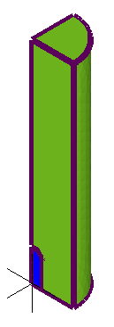
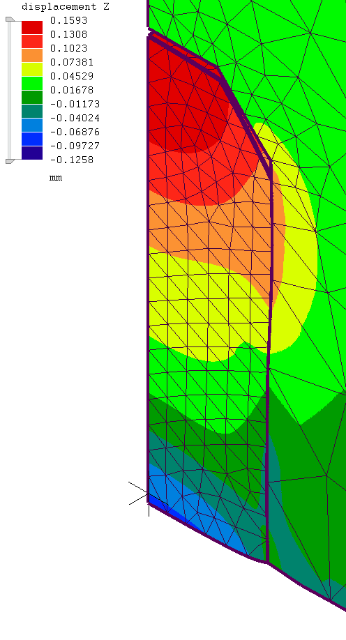
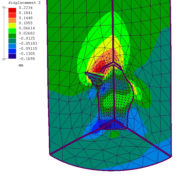
A stud (slave) mesh of 1 mm was chosen so that it would be smaller than the cylinder (master) mesh at the bonded surfaces. The resulting stud displacement (at the stud bottom centerline) is -0.0766 mm. (Model Static_elastic_bonded__1e12_GPa__12a.liml) Note that the top of the stud has a positive displacement (+0.1590). For the steel stud to have opposite displacements at opposite ends isn't reasonable.
Although the lateral edges of the stud appear to be well bonded to the cylinder, the bottom view (Z-displaced) shows that there are noticeable bonding gaps around the periphery of the stud.
If the stud mesh is 0.5 mm then the stud displacement (at the stud bottom centerline) is +0.01195 mm. (Model Static_elastic_bonded__1e12_GPa__11a.liml) Not only does this value not agree with the above but the sign is wrong since the negative pressure should cause a negative displacement. Also, note the lateral impingement of the aluminum cylinder into the stud, about half-way up the stud. The steel stud should be sufficiently stiff to resist such impingement and the shape of the impingement is simply unnatural. Also, note the odd deformation at the bottom of the stud OD where it attaches to the aluminum cylinder.
I thought this might be some odd consequence of Poisson coupling so I set this value to 0.01 for both materials. However, the resulting stud displacement was still positive (+0.0181).
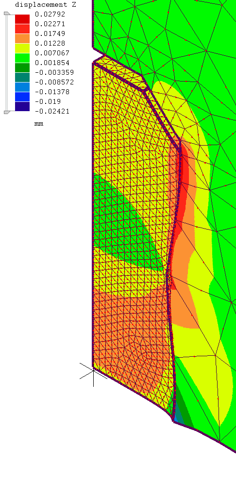
For the 1 mm stud mesh I tried replacing the frictionless supports on the lateral sides of the cylinder and stud with 1e20 GPa/m elastic supports. (Model Static_elastic_bonded__1e12_GPa__20a.liml) The gaps at the bottom periphery of the stud have been eliminated. However, the Z-displacement field is now asymmetric and there is a weird displacement spike at the top of the stud on the YZ plane.
I know this is a bit much to digest but I would appreciate any help.
Mecway 15.0
Thanks,
Don Culp
The top and lateral sides of the cylinder have frictionless supports.
The lateral sides of the stud have frictionless supports.
Bonded elastic contact 1e12 GPa/m between the cylinder and stud. (I chose this value because it seemed to work well for a previous modal analysis.)
-1 MPa pressure is applied to the bottom of the stud (i.e., the pressure is in the negative Z direction so as to elongate the cylinder).
ccx solver (I tried solving with the internal solver but it gave "Error: incompatible constraints" for a large number of nodes.)
Problems --
A stud (slave) mesh of 1 mm was chosen so that it would be smaller than the cylinder (master) mesh at the bonded surfaces. The resulting stud displacement (at the stud bottom centerline) is -0.0766 mm. (Model Static_elastic_bonded__1e12_GPa__12a.liml) Note that the top of the stud has a positive displacement (+0.1590). For the steel stud to have opposite displacements at opposite ends isn't reasonable.
Although the lateral edges of the stud appear to be well bonded to the cylinder, the bottom view (Z-displaced) shows that there are noticeable bonding gaps around the periphery of the stud.
If the stud mesh is 0.5 mm then the stud displacement (at the stud bottom centerline) is +0.01195 mm. (Model Static_elastic_bonded__1e12_GPa__11a.liml) Not only does this value not agree with the above but the sign is wrong since the negative pressure should cause a negative displacement. Also, note the lateral impingement of the aluminum cylinder into the stud, about half-way up the stud. The steel stud should be sufficiently stiff to resist such impingement and the shape of the impingement is simply unnatural. Also, note the odd deformation at the bottom of the stud OD where it attaches to the aluminum cylinder.
I thought this might be some odd consequence of Poisson coupling so I set this value to 0.01 for both materials. However, the resulting stud displacement was still positive (+0.0181).
For the 1 mm stud mesh I tried replacing the frictionless supports on the lateral sides of the cylinder and stud with 1e20 GPa/m elastic supports. (Model Static_elastic_bonded__1e12_GPa__20a.liml) The gaps at the bottom periphery of the stud have been eliminated. However, the Z-displacement field is now asymmetric and there is a weird displacement spike at the top of the stud on the YZ plane.
I know this is a bit much to digest but I would appreciate any help.
Mecway 15.0
Thanks,
Don Culp
Howdy, Stranger!
It looks like you're new here. If you want to get involved, click one of these buttons!
Comments
I’m not sure to correctly understand your simulation purpose.
¿What do you want to know? .
I think that once you finish , you will not get more than the confirmation of something you already know. Maximum pulling force = Friction force between pin and hole.
If you are planning to later introduce the deformed mesh from modal , that's seems much more interesting.
Regarding the type of contact you are using notice that the only force in this problem able to balance a pulling force downwards (Fz) is friction (Frz). No matter how much you press the pin. If you haven't set friction you do not test the strenght of the contact (slip test), you test the material strengh.
I would set up Nonlinear, Contact (elastic + friction) and an increasing pulling force with Quasestatic to check when it slips.
Look at the end of https://mecway.com/forum/discussion/1107/interference-fit-pressure-comparison-mecway-calculix-ansys
Take into consideration that Pressure as load will not provide you a linearly increasing pulling force as it depends on the surface which will vary due to Poisson’s ratio. I think nonlinear solvers in Calculix are isochoric (Poisson ratio almost 0.5)
One combination that works is the default option in bonded contact together with elastic support of Static_elastic_bonded__1e12_GPa__20a.liml.
I have done a set up I like to use when there is symmetry of revolution. Displacement (-y,x,0)=0. It is equivalent to set the rotation around the z axis =0. It removes the warning about incompatible BC. The Z axys needs special treatment.
By other hand , I have removed any link to the original surface. There were small deviations of the faces you can see selecting the hole surface and asking for the node’s coordinates. Now result looks clean and symmetric.
Then I have adjusted the contact surfaces to the desired radio to have an initial interference of 0.01mm. Slave external radius moved to 6.36mm.
I have set up a Contact with friction as recomended on my previous post. I have set up the initial Contact Pressure playing with the initial penetration 0.01 and Normal stiffness 410 GPa/m as example. Contact should slip at 200 N. It slips at 203 N. As it is a 1/4 model final real world magnitudes should be bigger (x4)
Regards
Victor -- You had recommended bonded elastic contact in several instances. As opposed to TIE bonding, you had reported --
- "The Elastic option in bonded contact should work reliably [my emphasis] with frictionless support." (https://mecway.com/forum/discussion/1136/using-frictionless-supports-with-a-bonded-contact-where-not-allowed?new=1)
- "The elastic option in bonded contact uses face-to-face contact and doesn't suffer from this problem. It's generally more robust [my emphasis] anyway so it might not hurt to use that instead. " (https://mecway.com/forum/discussion/comment/4842/#Comment_4842)
Can you pursue this problem further so that others who use bonded elastic contact can be reasonably assured that their results will be correct?I tried your suggestion about using default bonding (with 1e20 GPa/m elastic supports).
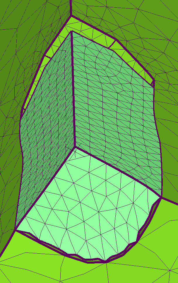
The displacement field is now symmetric comparing the XZ and YZ planes and the general displacement looks conceptually correct. See the progression of the following zoomed images. Note in the last image that there remain two small gaps at the bottom of the stud. In this case the gaps may not affect the results. However, in other analyses perhaps such gaps might be larger and could affect the results. How would I know (particularly, for instance, if this were a full 3D model where the gaps couldn't be seen)?
The problem I see is that there are three bonding options (default, elastic, TIE) and none seems completely reliable. Please correct me if I'm wrong.
disla -- Perhaps I should have mentioned my purpose. This would have saved you some effort for which I apologize.
Excuse me if some of my comments seems obvious to you, I’m also thinking in less experienced readers too.
-You can review the Contact Displacement/Clearance value at any time step if you hide the master (right button/hide) in the Solution/Component.
This exposes the slave face. If you set the maximum Contact Displacement/Clearance threshold in 0 you will detect detached areas.See Picture.
-Of major importance. I would be sure that I use values that are realistic. ¿Is Normal Stiffness of 1e20GPa/m realistic?. ¿How would I achieve this in real life?
-The springs stablished between the two surfaces by Bonded contact acts in the two directions. If the external force tends to open the gap, you should keep in mind that you can Keep closed the gap with a high normal stiffness in the simulation but , ¿how will you achieve this in real life?. ¿Are you planning to glue the two surfaces?. Maybe it’s a good idea to keep a low Stiffness to detect those areas.
-I see initial penetration like a prestress in a bolt. It provides a uniform Contact pressure able to absorb future deformations without detach/opening.
If you set up both surfaces with the same radius 6.35mm, Contact pressure will be very low.
-FEM is a discrete method. Between two nodes there will always be a straight line and between two meshes with different density there will always be gaps, no matter TIE or how high is the Normal Stiffness.
If you are only interested in keeping both surfaces perfectly together, ¿have you consider a conformal mesh?. There is not even the concept of gap or contact.
I tried the following under "CCX\custom step contents" but couldn't get CDIS to display in the solution tree for this static analysis.
*END STEP
*STEP,PERTURBATION
*NODE FILE,GLOBAL=YES
U,S,CDIS,CSTR
** U=displacement; S=stress; CDIS=contact displacement; CSTR=contact stress
Could you post your model? I would then have some comments.
Thanks,
Don C.
Picture shows model without initial penetration and Bonded Contact and model with initial penetration of 0.01mm and Contact for the same range of stresses.
From your "Pull Test Static.liml", could you explain what the boundary conditions in this image mean? I understand NALL but not how "-y" and "x" are used.
More questions later.
Unfortunately, the reason there are 3 options is that none of them are the best in every way. Elastic avoids the common and often random-looking problem of MPC conflicts. That's why I've called it robust. But this complete borking is a surprise, especially for such a simple model.
I don't think those gaps you identified are really gaps. The contact surface of each element is a higher resolution triangulation of element face than what the display shows so it can follow curved deformation that looks like straight half-edges in the deformed view.
@disla, strange that it seems to work right with an initial penetration, if I'm reading your solution correctly?
"The contact surface of each element is a higher resolution triangulation of element face than what the display shows so it can follow curved deformation that looks like straight half-edges in the deformed view."
The image below shows another view of the bottom of the stud (deformed model, scale factor 1e5). For default bonding, Mecway's manual (p. 63) states, "Mecway projects each slave node onto at most one master face. The slave node is then constrained to move and rotate along with its projected point." However, on the lateral surface of the image below, the stud's slave node is not attached to its projected point on the master mesh, thereby leaving two distinct "gaps". On the other hand, the projection seems to work correctly for the circular row of nodes on the bottom. (The master elements on the lateral faces and bottom faces are approximately the same size; same for the slave nodes. Thus, this shouldn't be why the bottom surface appears to be correctly bonded while there are "gaps" in the lateral surface.) Am I misinterpreting the manual or is projection not working correctly in this case?
Also, if you zoom on the two "gaps" you can see interior nodes and elements which would indicate to me that such "gaps" are real (scale factor 5e5).
Even at this scale factor the bottom nodes don't show any similar gaps.
In any case, this again begs the question of how to detect bonding gaps. (Also see discussion with disla (toward bottom) for which I have yet further questions when time allows -- https://mecway.com/forum/discussion/1095/ccx-solver-and-modal-calculation#latest)
With the *TIE option, CCX generates a list of non-connected nodes in the file WarnNodeMissTiedContact.nam that's placed in the CCX working directory. Set Tools -> Options -> CalculiX -> Same as the .liml file to make it more accessible. Also, the solver output show warnings like:
(x,y,z) is a vector that goes from cero to the point. Radial direction.
(x,y,0) is a vector that goes radially but constrained into the XY Plane. Radial direction in cylindrical coordinates.
(-y,x,0) is a vector perpendicular to (x,y,0). Tangential direction in cylindrical coordinates.
You can do crazy stuf with this.
When position tolerance for tie was set to 0, there would be parts which was not connected but when the position tolerance was set to 1mm, then it bonded the whole surface as intended.
I reran the model with TIE bonding and looked at WarnNodeMissTiedContact.nam. With a position tolerance of 0.1 mm there were 22 unbonded nodes. These can be seen on the slave surface of the stud (blue dots) --
To visualize the unbonded nodes --
1. In WarnNodeMissTiedContact.nam the unbonded nodes are listed in a column. Convert this column to a horizontal list with each value separated by a comma. (This can be fairly easy depending on your editor. I use EditPad Pro.)
2. In Mecway, paste this list into "\Edit\Select nodes by number".
3. In the Solution, hide all components except the one that contains the slave surfaces.
4. Orient the model as needed to see the unbonded nodes.
With a position tolerance of 0.15 mm the number of unbonded nodes was reduced to 2; then reduced to 0 at 0.16 mm (same results up to 1.0 mm). With 0 unbonded nodes the deformed image at the stud-cylinder boundary was the same as above for default bonding. Thus, your conclusion seems correct -- the visual "gaps" on the lateral bonded surfaces apparently aren't real.
This has been resolved by changing the solver from CCX to Mecway internal (see attached model Static_elastic_bonded__1e12_GPa__21b.liml).
The bonded contact indicates that there is a problem, "Elastic is not allowed with this solver. Use the CCX solver." However, the displacements are now consistent with TIE bonding (when using an appropriate TIE position tolerance).