Stuck?  support@mecway.com
support@mecway.com
Mecway
FEA
CCX solver and modal calculation

Hello, I have a problem with the CCX solver.
Mecway version 14.0 64 bit, Elements: 279445 Nodes: 583784, Elements type: TRI6, QUAD8, TET10
I am trying to do a modal calculation right now.
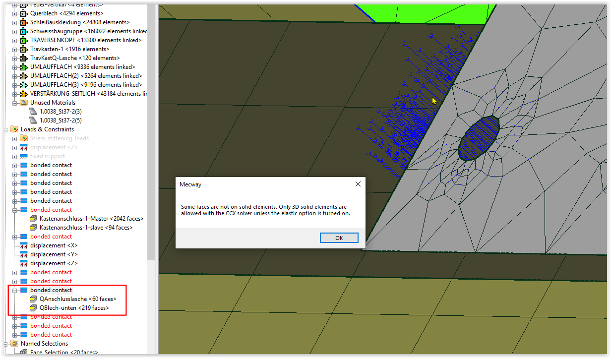
Bonded shell surface-to-surface and solid-face (master) to shell edge (slave) are not working. What am I doing wrong?
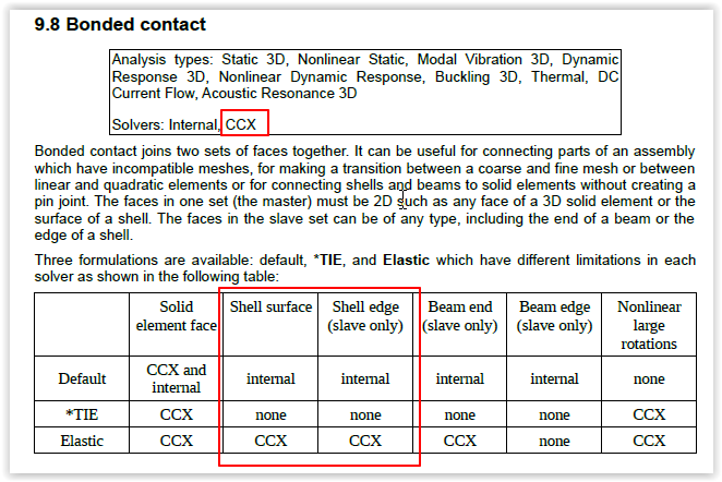
In the manual it is described that it is allowed.
Thanks for the help :-)
Mecway version 14.0 64 bit, Elements: 279445 Nodes: 583784, Elements type: TRI6, QUAD8, TET10
I am trying to do a modal calculation right now.
Bonded shell surface-to-surface and solid-face (master) to shell edge (slave) are not working. What am I doing wrong?
In the manual it is described that it is allowed.
Thanks for the help :-)
Howdy, Stranger!
It looks like you're new here. If you want to get involved, click one of these buttons!
Comments
https://joest.dataservice.zone/f/18c7f42fe23a4d90a472/
I see some possible conflict points:
1-There are some Springs defined as Truss and with an empty section definition in the general material window.
2- Three of those springs have a custom V axis aligned with the elements. It should be perpendicular.
3-Kastenanschluss-1&2-slave have faces that are outside the master Kastenanschluss-1 & 2-Master.
“The surface with the larger area should be the master. If the slave surface overhangs the edge
of the master surface then slave nodes which are too far from the edge won't be connected.”
4-The model seems broken at the seam line shown on the picture. Open Cracks to check.
5-¿Is elastic contact compatible with modal analysis?
6-Which are the BC that constrain the body with respect to the external reference system. ¿Is it completely free.?
7-Repartur bonded contact has some issue.
I suggest you proceed computing just 1 mode and advance adding the contacts one by one to find which ones work and which ones not.
thanks for the comprehensive report.
I check the issues step bye step.
But the thing is, the mecway internal solver works fine and given a solution and the CCX solver can’t start and failed?
Best regards
Dieter
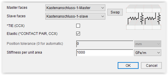
Elastic (which is *CONTACT PAIR with *SURFACE BEHAVIOR,PRESSURE-OVERCLOSURE=TIED) doesn't work with modal. I'm not sure why. It should be mentioned in the manual but isn't, sorry. I just confirmed it on a simple solid model and it didn't join the parts together at all.
*TIE and neither option don't work on shell edges.
The internal solver's bonded contact uses constraint equations on the rotational DOFs of shells but CCX doesn't allow you to specify constraint equations using rotational DOFs.
The same problem had dculp --see here--
Therefor I wrote 1e15 Pa/m elastic support in bonded contact.
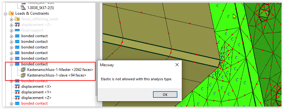
The text is red and the message "whats wrong" called "Elastic ist not allowed with this analysis type". But the solver works. I hope I get a solution
EDIT: Even simpler way but I have no idea why it works. Add the PERTURBATION parameter to the *STEP keyword. Here's an example.
Really awesome work. The more I look at it the more I realize how much work you invest. Thanks for sharing. The forum is a nice source of tricks and knowledge for me.
I have computed the modes using PERTURBATION and it seems to work.
First 1 & 2 Mode are related with the free Querblech motion. Seems it needs some adjustment as faces are too far.
*WARNING in gentiedmpc: no tied MPC
generated for node XXXXX opposite master face found but too far away; distance: 0.15249999999932029 tolerance: 7.9667589421474663E-005
Supressing Querblech I have found 3 modes that seems rigid body motion corresponding to the 3 springs and then 9 that seems to have sense as they all show symmetry.
Model without Querblech in pastix runs in 9 minutes. It's ok to know all the rest works.
I will try to solve with Querblech.
I have add the PERTURBATION parameter to the *STEP but now theres an error:
*ERROR in u_calloc: error allocating memory variable=eme, file=arpack.c, line=380, num=739872144, size=8
Do you have a ideas whats wrong?
Modal solver with 13 natural frequency. 279440 Elements and 583772 Nodes.
With the CCX-PARDISO solver it works 13 minutes on my laptop Precision 5560. Thats perfectly.
Thank you all for your help.
Kind regards
Dieter
You can download the final model -click-
"Even simpler way but I have no idea why it works. Add the PERTURBATION parameter to the *STEP keyword. Here's an example."
Your example works for your shell elements. However, when I tried this on a 3D model (attached), there was no bonding between the stud and cylinder. There were no error messages during the analysis. However, there was a warning --
" *WARNING reading *STEP: parameter not recognized: PERTUBRATION"
This didn't occur in your example but instead --
" *INFO reading *STEP: nonlinear geometric effects are turned on"
The following image is for mode 5.
Perhaps this method doesn't work for 3D elements?
Mecway 15.0, Windows 10, CCX analyzer
Thanks,
Don C.
Your comment of Feb 15 -- "You just need to put any load on it, along with the necessary constraints for a static analysis and that activates stress stiffening which causes elastic bonded contact to work. I've confirmed it with a small solid model."
This works very well (better than any other method I've tried) to insure proper bonding (no gaps) for modal analysis. However, it doesn't allow stress calcs, at least for modal analysis. The stress "What's wrong" warning is, "Stress is not generated when stress stiffening is applied".
See the attached model where a 1N load is applied in the Y-direction at (0,0,0). The elastic bonded contact is between the short stud and the cylinder. (The following image shows the displaced model for mode 4.)
Mecway 15.0, CCX analyzer, Windows 10
Thanks,
Don C.
Remember of course that this is not really stress but proportional-to-stress with arbitrary scaling at each mode.
Can you upload the modified model?
(Yes, I understand about stress scaling.)
Thanks,
Don C.
Vm and Stress is in red, but it works.
This version is slightly different than Victor's proposal.
It allows Mecway to generate the load cards and only adds the frequency at the end as an additional Step.
Your "custom step contents" are --
*END STEP
*STEP,PERTURBATION
*FREQUENCY
5
*NODE FILE,GLOBAL=YES
U,S
Does the "5" refer to the required number of modes to be extracted? If so, must it agree with the value in "Analysis settings" or does it override that value?
Also, what does "U,S" mean?
Note -- For an elastic bonded stiffness of 1e6 GPa/m, the top of the stud is not attached to the cylinder - see mode 3, the yellow von Mises area in the image. (Swapping master-slave had no effect, as I expected.) This improves at 1e9 GPa/m and seems to be resolved (at least visually) at 1e12 GPa/m.
Mode 3, 1e6 GPa/m --
Mode 3, 1e9 GPa/m --
Mode 3, 1e12 GPa/m --
This gap isn't very evident in mode 4 (the desired mode) and could easily be overlooked.
I haven't seen an easy way to detect/flag such gaps. JohnM suggested using a simple pull test (https://mecway.com/forum/discussion/comment/4842/#Comment_4842) but this adds an additional modeling step.
Thanks,
Don C.
-Right. 5 is the number of modes required to be extracted.
-There is no need to agree. I suggest to set Mecway Analysis setting to 1.
-No, it is not overridden.I would say Mecway computes the number of modes indicated in the Analysis settings and then it computes again the number of modes requested in the custom card. (It appears twice in the inp). Yes, it is computed twice. You may ask ¿why?. This way you don’t erase and have to rewrite the Static.. step card that contains the loads again with possible mistakes.
-"U,S" mean you request nodal displacements and stresses.
I did’n understand why you were not using Tie. Your last question responds it. I would try adding CDIS (relative contact displacements) and CSTR (nodal contact stress) into the requested output variables. I think they can help you to find those low contact areas or excessive gaps. Not sure but I suppose those values are not real and arbitrary scaled as the other stresses.
*NODE FILE,GLOBAL=YES
U,S,CDIS,CSTR
NOTE: Take a look at ccx manual v2.19 , 6.13 Output variables. Just once to have a general idea of the available information.