Stuck?  support@mecway.com
support@mecway.com

Mecway
FEA
Modelling of bridge bearing devices

Hello,
I am trying to model a two-span bridge deck supported by a central frame pier in Mecway.
The beams are supported on the central pier through bearing devices with different constraints. Specifically:
- The two outer bearings provide vertical support only, allowing horizontal movement.
- The central bearing provides both vertical and transverse restraint, while allowing longitudinal movement.
I would like to know how these bearing conditions can be correctly modelled in Mecway. In particular, which constraints or boundary conditions should I apply between the deck and the pier elements?
Thank you in advance for your help.
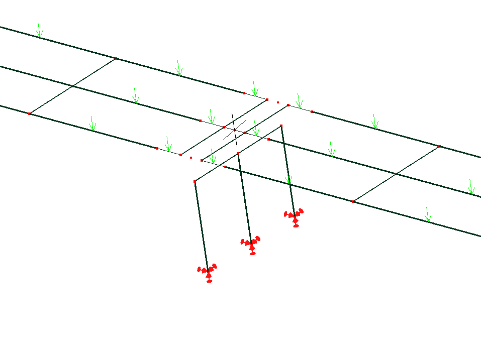
I am trying to model a two-span bridge deck supported by a central frame pier in Mecway.
The beams are supported on the central pier through bearing devices with different constraints. Specifically:
- The two outer bearings provide vertical support only, allowing horizontal movement.
- The central bearing provides both vertical and transverse restraint, while allowing longitudinal movement.
I would like to know how these bearing conditions can be correctly modelled in Mecway. In particular, which constraints or boundary conditions should I apply between the deck and the pier elements?
Thank you in advance for your help.
Howdy, Stranger!
It looks like you're new here. If you want to get involved, click one of these buttons!
Comments
This way you could define that the vertical displacement of the outside deck nodes must always be the same as the vertical displacement of the corresponding support frame nodes.
Same aoplies for the central nodes with vertical and transverse displacement.
I think you will have to define one constraint equation for every node pair and constraint direction such as z1 - z2=0.
To clarify the issue, consider the bridge with one of the two spans removed. Because of the eccentricity between the beam end and the pier axis, each beam should transmit to the pier both a vertical force and a moment, with the latter equal to the vertical force multiplied by the eccentricity.
However, I cannot obtain this moment in my Mecway model.
Other FEA software allows the use of rigid links to connect nodes, which would naturally account for the eccentricity and transfer both forces and moments. I am wondering whether Mecway has a similar feature or whether there is another recommended way to model this type of connection.
Constraint equations can couple moments but you have to write it into them which is a bit fiddly. See picture and attached file.
Node-surface coupling with the RBE2 option can connect the ends of two beams together but doesn't have options for releasing individual DOFs - only all rotations at one end or nothing.
- The central bearing provides both vertical and transverse restraint, while allowing longitudinal movement."
vertical (z)
transverse (y)
longitudinal (x)
Bridge decks are underconstrained in Longuitudinal direction (x) ¿isn't it?
I also tried to introduce flexible joint on beams:
- For the two outer bearings, that provide vertical support only, vertical truss elements should work.
- For the central bearing, which provides both vertical and transverse restraint, how can I contraint the transversal displacement only by means of releases?
@disla
The longitudinal contraint is on the the bridge abutment, so to have a statically determinate system.
"The longitudinal contraint is on the the bridge abutment"
Then it's not completely free to move in x but must keep on top of bridge pier. (Friction would do the job).
Attached how I conceptually see the problem. Note that unrestrained beams on x direction in outer area may slip from the abutment. A roller is assumed there.
No moments are allowed to be transferred more than those due to the eccentricity of the beams contact area with respect to the pier axis. That assumes bridge bearings in pier function as structural hinges.
@disla
I’m not sure I understand what you mean. Each span of the deck is constrained at six points: three supports are located on the abutment and three on the pier.
The central beam has a hinge at the abutment and a longitudinal bearing device at the pier, which prevents transverse and vertical movements. The outer beams have vertical supports at both the abutment and the pier.
Therefore, each span is statically determinate. This is a fairly common configuration for bridges.
the central beam is fixed at the abutment but may elongate longitudinally without any contraint.
"Longitudinal bearing device at the pier , which prevents transverse and vertical movements. "
Do you mean this "Longuitudinal bearing device" prevents only transverse and vertical but not longuitudinal displacement. Do you mean a roller in x direction?
¿I assume it is additionally free to rotate?
EDITE: FILE in LAst Post.
Each beam is supported at both ends according to the attached bearing scheme. For the central beam, the support on the pier is provided by a unidirectional bearing, which allows longitudinal displacement and rotation while restraining transverse displacement. In this sense, it behaves like a roller bearing, but only with respect to longitudinal displacement.
rom a technological point of view, several solutions are available for manufacturing this bearing device. The one shown in the picture is one of the possible solutions, although it is now considered obsolete.
Anyway, we are going off topic.
I have already modelled the bridge by connecting the beam-end nodes at the pier using constraint equations. However, as I mentioned, this modelling approach does not capture the additional moment generated by the eccentricity of the beam reaction relative to the pier.
Therefore, my question is: how can I correctly capture this moment at the pier?
I initially tried using rigid elements, but, as shown in the model, the axial load in the pier is significantly lower than expected. This seems to indicate that the rigid elements are providing an alternative load path that bypasses the pier.
Here it is again . Same config but with beam elements.
Since the pier is modelled using brick elements and the constraint equations link the forces between the beam nodes and the pier nodes, the model introduces the moment I was looking for.
Unfortunately, I need the pier to be modelled using beam elements instead of solid elements.
I think it should be possible to work out the problem using rigid beam elements, but I can't figure out why the loads in the pier decrease abruptly when I use them.
Is this behaviour correct?
I would have expected the axial load carried by the pier not to depend on the stiffness of the rigid elements in this particular configuration.