Stuck?  support@mecway.com
support@mecway.com
Mecway
FEA
How to connect/weld parallel Beam Elements (unifilar model) without shared nodes?

Hello everyone,
I am working on a structural model in Mecway using Beam Elements (wireframe model). I have a specific question regarding how to simulate a welded connection between components that are physically separated in the geometry.
My Scenario:
I have a 'sandwich' assembly consisting of:
A top square hollow section (tube).
A flat bar in the middle.
A bottom square hollow section (tube).
In the real world, the flat bar is welded to the outer faces of both the top and bottom tubes. However, since I am using line elements, I don't have physical surfaces to select and use the Contact (Bonded) command. When I run the solver, the three elements act independently and the load is not transferred.
My Question:
What is the best 'standard procedure' to 'glue' or 'weld' these parallel lines together so they act as a single rigid unit?
Should I use Rigid Constraints (RBE2) to link the corresponding nodes vertically?
Is there a way to create an automatic link or coupling between these parallel lines?
Or is it better to create manual 'connector' beam elements with very high stiffness (high Young's Modulus) to simulate the weld?
I am looking for a reliable way to ensure the 'sandwich' works together without having to model the entire structure as solids.
Any advice or 'recipe' on how to set this up correctly would be greatly appreciated.
Thank you!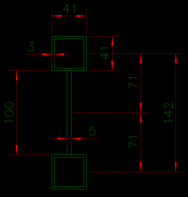
Howdy, Stranger!
It looks like you're new here. If you want to get involved, click one of these buttons!
Comments
I am a Project Engineer performing a structural validation of a spreader bar. I have already prepared the following:
A complete wireframe skeleton modeled in Mecway.
The corresponding AutoCAD 3D wireframe for reference.
A custom cross-section in AutoCAD (DXF) consisting of two square tubes joined by a flat bar.
The Problem:
I need this custom section to follow the entire perimeter of the lower frame of my wireframe. However, I am stuck on the following points:
Workflow: Should I import the section first and then assign it to the lines, or must the lines be converted to a specific element type (like Beam) before they can receive this geometry?
Path Mapping: How do I make this specific DXF profile run or sweep along the entire length of the lower lines automatically?
Interface Issues: My version does not show 'Properties' in the component right-click menu, making it difficult to switch from Line to Beam.
I am validating equipment that has already been manufactured, so I must use the exact geometry of this 'sandwich' section to get accurate stress and moment of inertia results.
Please provide a detailed step-by-step on how to map this DXF section onto my existing wireframe.
Thank you,
Marcos