Stuck?  support@mecway.com
support@mecway.com
Mecway
FEA
Step-by-step help needed: Bolt Pre-tension on split vs. solid geometry (CalculiX)

Step-by-step help needed: Bolt Pre-tension on split vs. solid geometry (CalculiX)
Body:
Hello,
I am struggling to get a reliable bolt pre-tensioning workflow in Mecway using the CalculiX solver. I have tried both a single-part bolt and a bolt split into two halves (modeled in Alibre Design).
Could someone provide a clear step-by-step on how to correctly apply the pre-tension? Here is my current situation:
Face Selection Issue: I cannot seem to apply the "Pre-tension section" to the internal cross-section face of the bolt. The option is often greyed out or gives a "Not available for this selection type" error.
External Surface Workaround: I only managed to activate the command by selecting the external cylindrical surface of the bolt. This creates the green vector, but I am unsure if this is the correct physical representation for a structural simulation.
Split Bolt Setup: When using a split bolt, should I use a "Bonded" contact between the two halves in addition to the pre-tension? Or does the pre-tension tool handle the connection automatically?
What I need is a definitive "best practice" guide:
Step 1: How to prepare the geometry (Solid vs. Split).
Step 2: How to ensure the internal face is "seen" by the mesh as a valid pre-tension section.
Step 3: Correct settings in the Pre-tension dialog (Force vs. Length).
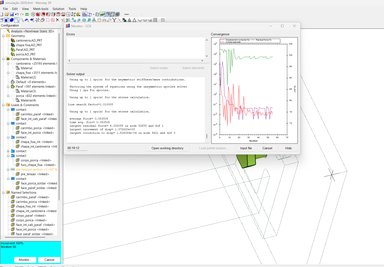
I've attached screenshots of my current model and the convergence monitor. Any help to stop this "trial and error" would be greatly appreciated.
Thank you,
Howdy, Stranger!
It looks like you're new here. If you want to get involved, click one of these buttons!
Comments
1. Don't split the bolt. Make it a single part. Mecway finds the faces for the split and CalculiX splits it.
2. I'm not sure what you mean but the split happens roughly in the middle of the prism (cylinder in this case). The ends of that prism are defined by the selection that the pre-tension section is applied to. In this case, it would be the middle of the half of the bolt that has the nut. Extend that selection to the whole shank if you want to make it in the middle of that.
3. Length adjustment is usually what you'd want for a bolt. It behaves similar to what a thermal strain would. It moves the two halves together by the specified distance. Force just pulls them together with a constant force that doesn't change with external loads. If the know the force that the bolt is torqued to, but not the length change, you can first solve with the Force option, then measure the length change from the solution and set that as the Length adjustment option and solve again.
Put some displacement constraints somewhere on the assembly to prevent rigid body motion.
One question: To simplify the model, can I use a Bonded (Tie) contact between the bolt head and the plate, and also between the nut and the plate? Or should I stick with sliding contacts?
Since I'm still learning the workflow, would you happen to have a very simple Mecway sample file (.liml) with a single bolt and two plates already set up?
I would like to open it and study the tree structure to see exactly how you've organized the pre-tension section and the contact pairs (Bonded for the head/nut and Sliding for the plates). It would be a huge help to have a reference model that is already working and converging.
-I think you have all the contacts in the 2nd example as unilateral (which i feel is likely to model most real life situations the best). My experience has been this set up rarely converges, my assumptions has been that there is some sort of free body motion that causes this. My approach to help convergence has been to cheat by locking the "free parts" in place with some trick (i have used springs, non linear springs and elastic supports and even friction with "imaginary" parts to do this)
-in situations such as the example shown here it does converge. I have a (perhaps wrong or at least controversial! ) theory, that in this case and others like it (where parts are very close or coincident) , this is only because there is some sort of interaction/connection between parts that suppresses free body motion.
-frequently I have been pleased (and sometimes amazed!) when a unilateral contact model converges, only to find out done the line I have made a modelling error and one or more parts collide. Once the interference is rectified the model no longer converges!
-My work flow in contact analysis now includes running the model with no external forces (in this case no pretension or plate loads), this often gives an indication that something is amiss. I also export an .stl to rhino and look to see if any parts "clash" - in this case they do. (this could be due to the export
converts the hex blocks to tets but it certainly appears to support my theory a little)
-I then took your model and move the bolt and nut faces 0.01mm away from the plates. (see attached file). Now (if no fixing tricks are used) the analysis will not converge. I cheated and used elastic supports on the nut and "free" plate and it will converge.
-interestingly enough it will also converge with no pretension or force with out showing high numbers of contact elements. In addition the "no extra contact step" is also no longer require.
one aspect that works against my theory is that "open cracks" and exploded view do not indicate any interface in this any other cases I have though had this issue.
-I will be keen to here if others have any thoughts on this
On a different subject I do not feel that the using "force" in the pretension analysis represents most real life situations as closely as using displacement. I imagine you only used it here for demonstrations purpose, in reality it is hard to think of a scenario where the bolt tension is kept constant thru the loading process.
If you preload the bolt with a force, it holds that force, even after the plates are being pried apart. Once the pry load exceeds the bolt preload, the plates separate and the solution crashes. This is not the correct behavior for the bolt.
If you preload the bolt with an equivalent length adjustment and apply load to pry the plates apart, the bolt load increases, as it should. This makes sense.
For soft/compliant joints this can require doing a dummy run to determine the equivalent length adjustment, but it's worth it.
I could not help but take a closer look at your model (I always like to see how others approach these type or problems). Interestingly, I think this could be another example of a model that potentially has some interference- my check suggest a possible clash -see screen shot. I moved the upper face of the plate down a little (to be sure of no interference). The analysis converges much quicker in this set up. Also it behaves a little differently when the analysis is run with no pretension or load
*STEP
*STATIC,TIMERESET
1,1,1E-06,0
*EL FILE
ENER
*END STEP
prior to your load steps so that all subsequent contacts are converged as the loading progresses (we often need this). I sometimes wonder if we could improve that initial contact step. If you suppress initial contact, you can see contacts actual pull themselves apart in the final steps - not always desirable.
Since many of our models are multi-part assemblies, they tend to need initial contact to keep from flying apart, so we accept the "iteration rattling" that we get at the beginning.
One note on your model - when you create the gap, add that amount into the length adjustment or you'll lose bolt pretension.
I'm facing some challenges meshing a large skid model imported from Alibre Design into Mecway.
The mesher fails to generate a mesh unless I use a very coarse element size (around 30mm). However, my model has structural beams with 8mm thick webs, so a 30mm mesh is too coarse to capture the geometry accurately.
I have two questions:
Is there a way to optimize the import or use local refinement to handle these thin sections without crashing the mesher?
Is it possible to model this type of geometry (beams with plate lifting lugs welded to the flanges) directly within Mecway? I know how to create beams, but I'm unsure about modeling the custom plate lugs attached to them.
Any guidance or tutorials on how to build this directly in Mecway or improve the current meshing process would be greatly appreciated.
Thank you,
Marcos"
Here is the complete text in English for you to copy and post. I have polished the grammar to make it sound professional for the Mecway engineering community.
Subject: Difficulty meshing large Alibre model and questions about modeling lifting lugs in Mecway
"Hello everyone,
I am working on a large skid project in Alibre Design and I'm having trouble importing it into Mecway for FEA.
When I import the solid model, the mesher fails to generate a mesh unless I use a very coarse element size (around 30mm). However, my skid has structural beams with 8mm thick webs, so a 30mm mesh is too large to capture the geometry correctly and leads to poor results.
I would like to know:
Is it possible to model the lifting lugs directly in Mecway instead of importing them as solids from Alibre?
If so, what is the best workflow to create a plate lug with a hole and attach it to the flange of a beam?
I am familiar with creating beam elements, but I'm not sure how to model the lug plates and ensure they are properly 'welded' or connected to the beams within the software to avoid these meshing issues with thin geometries.
Any guidance, tips, or step-by-step instructions would be greatly appreciated.
Thank you,
Check this two examples
Skid analysis using hexa meshing
http://mecway.com/forum/discussion/725/skid-analysis-using-mecway-salome-calculix#latest
Skid analysis using hexa meshing and beams elements
http://mecway.com/forum/discussion/760/skid-analysis-using-hexa-vs-beam-elements#latest
In this example, the applied force is 3000N, and causes a deformation of 0.455mm. In the displacement drived condition, the displacement applied is 0.455mm , but the displacement achieved is 0.366mm