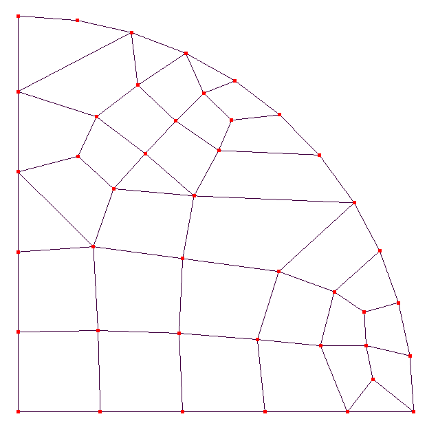
Surface mesh with poor element (nearly colinear nodes)
The attached model generates the following surface mesh for quad dominant elements. Note the element in the upper left which has nearly colinear nodes along the curved boundary of the model. The same mesh results with either the internal mesher or Netgen 6. The meshers could correct this by specifying a maximum included angle between adjacent sides (e.g., all included angles less than 135 degrees). If such a quad element isn't possible at that location then it should be split into two triangular elements. (Of course I could manually adjust the meshing parameters to correct this problem but this shouldn't be necessary.)


Howdy, Stranger!
It looks like you're new here. If you want to get involved, click one of these buttons!

Comments
Also, see my latest post (gmsh - How to change the 2D quad element size?) which uses the same step file.
Note that the problem mesh discussed here was generated by Mecway 18, not gmsh.
My intent with these 2D quad meshes is to eventually extrude in the Z direction to produce 3D hex mesh.
Your custom commands work well. However, they generate additional nodes at the center of the elements. (I don't understand why these nodes were generated or what they are for since they aren't connected to anything.) These can be deleted by \Mesh tools\Delete unused nodes. Is there a custom command that will do this automatically?
The following shows the result (before deletion) where, tor simplicity, the mesh had been generated without midside nodes. The model with these additional nodes is attached.
Edit 2/12/2013 -- It seems that the additional nodes aren't generated if the elements aren't quadratic.