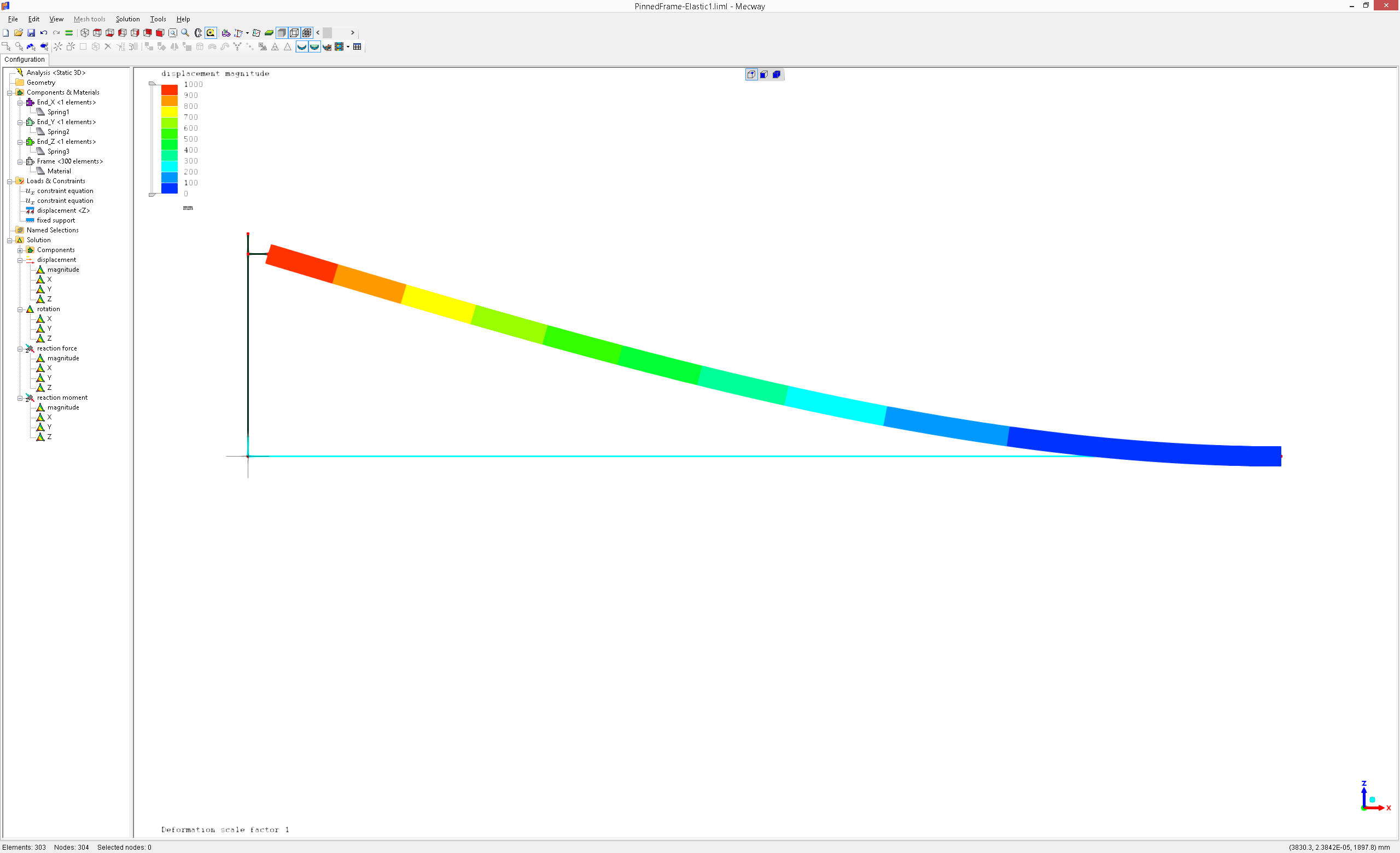
Pinned-clapped frame analysis.
Good morning to everyone:
I enclose you a simple model to depict how to model a pinned-clapped 5meters frame using MECWAY internal solver and constraints equations.
About the file attached:
MANUEL
P.D. Thanks to Victor for his help for suggesting modelling the end-release using constraint equations.
I enclose you a simple model to depict how to model a pinned-clapped 5meters frame using MECWAY internal solver and constraints equations.
About the file attached:
- The analysis was done using MC13.0+internal solver(this lets you use constraints equations of the kind A*dof+B*dof+...=D.
- CCX imposes D=0.0 which will not let me raise the end release node).
- The model was done using the internal drawing engine (typing coordinates and remeshing).

MANUEL
P.D. Thanks to Victor for his help for suggesting modelling the end-release using constraint equations.
Howdy, Stranger!
It looks like you're new here. If you want to get involved, click one of these buttons!

Comments
I enclose you a scheme(brief summary) of the model of the partially release end frame.
I need the MPC to transfer displacements from end of the frame which is a theoretical zero-length joint until the rest of the 3d frame. With this 3d model of the ends of the frame I can simulate elastic unions(pinned, partially clamped, ...)
MANUEL
This is how I would normally simulate Pinned and Clamped beam connection as a whole.
The effect is clearly seen on the main beam deformation.
Keep i mind that for the main beam, stresses can be underestimated when using beam elements. Manual says:
-"Stress in element coordinates are evaluated at each of 4 predefined points in
the cross-section and one user-defined . These stress values are calculated only from the normal force and bending moments. They do not incorporate shear stress caused by torsion or shear forces"-
Regards
Thank you very much for your comments and your contributions.
You are absolutely right, the beam element used in MC engines only considers axial and flexural stiffness. Besides, I also wanted to include rotational springs into the MC model but I couldn’t. But it does not matter.
The main purpose of my prototype was to model a partially rigid connections in beams. Incomplete in this case due to the lack of rotational springs.
So, after that, and for educational reasons, I coded a python script to solve the K_e(stiffness matrix of a beam) for 3d partially rigid beams(translational and rotational degrees of freedom) and it worked.
I assembled it all using LAGRANGE MULTIPLIERS, static condensation and finally the python function returns me the local stiffness matrix of the beam considering semi rigid ends. I attach you the declaration of the function. You will notice that I included a "k_infinite_displacement" and "k_infinite_giration" parameters to set "infinite value" in order to force MPC(Multi point constrains).
After solving the k_e matrix, I went ahead with the mass(M) and consistent(C) matrices. Actually in testing but seems to work.
def calculate_ke_local_Condense(l:float, E:float,nu:float,
Ax:float,Asy:float,Asz:float,
Ixx:float, Iyy:float,Izz:float,
dAlfa:float,
dY_ShearCenter_from_C:float, dZ_ShearCenter_from_C:float,
iNumPieces:int,
k_1_dx:float,k_1_dy:float,k_1_dz:float,k_1_gx:float,k_1_gy:float,k_1_gz:float,
k_2_dx:float,k_2_dy:float,k_2_dz:float,k_2_gx:float,k_2_gy:float,k_2_gz:float,
k_infinite_displacement:float=1e10, k_infinite_giration:float=1e10,
bK_g:bool=True,bM_e:bool=True,bC_e:bool=True,alfa_R:float=1.0,beta_R:float=1.0)->np.array:
MANUEL
Let us know if you get some progress.
Your name is MANUEL. ¿Are you Spanish? ¿Are you student?
Regards
My name is MANUEL MARTÍN, spanish architect specialiced in structure calculation.
(I am not a student, I'd wish I could be one, but not).
I will let you know about the progress in my library!!!
Regards
MANUEL