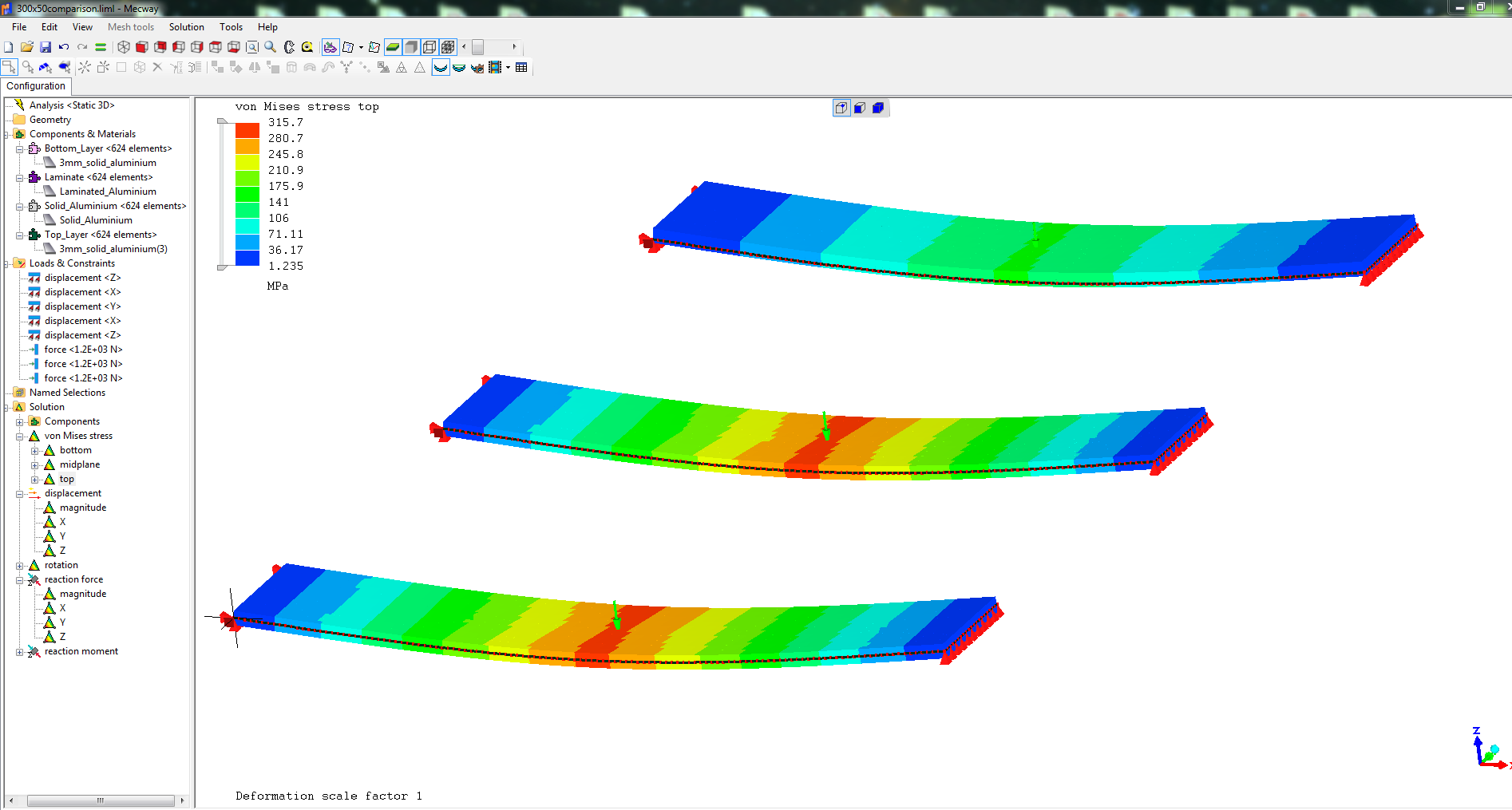
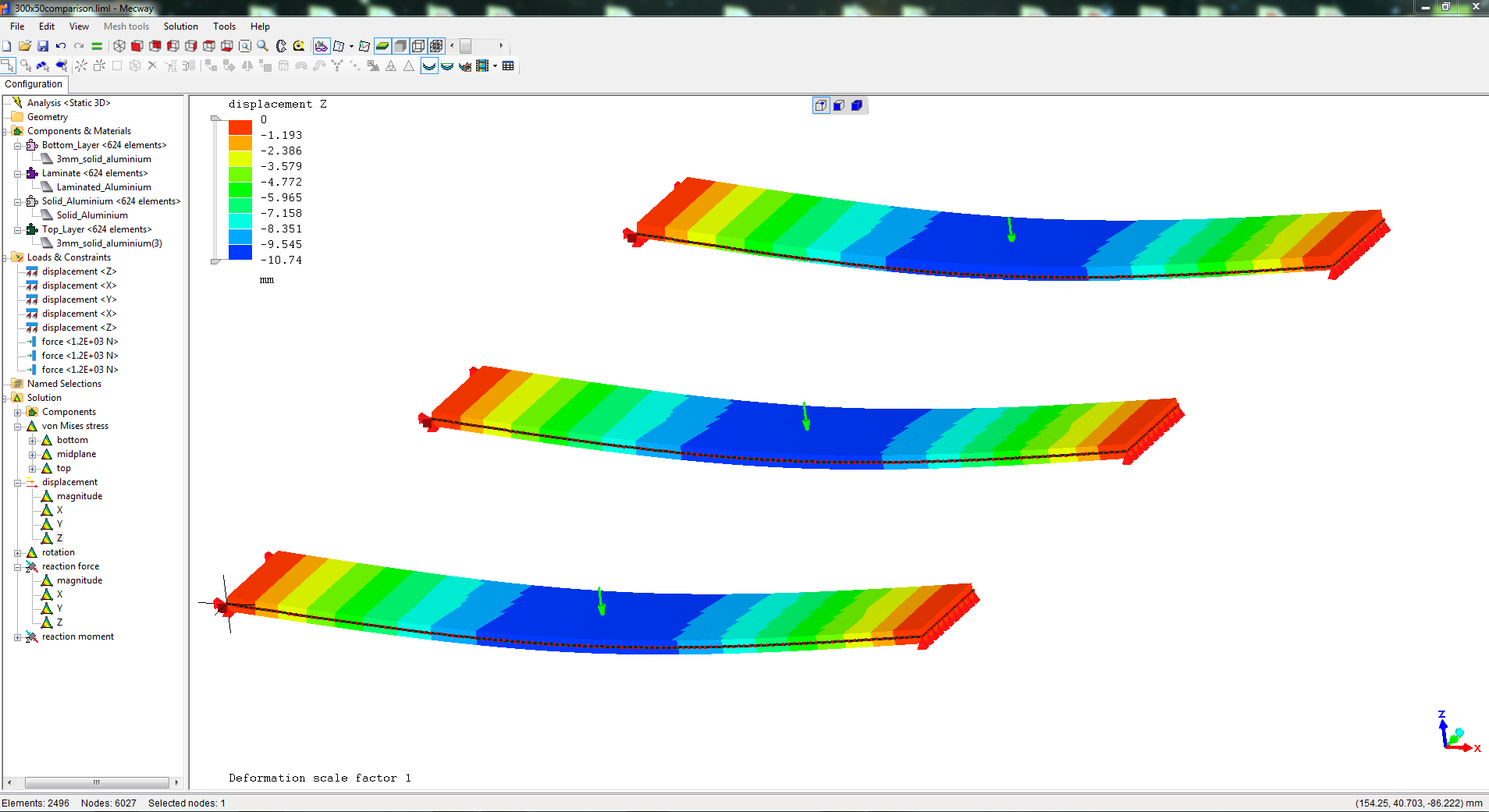
Deflection of bar using 3 different methods: - laminations, solid, merged nodes/shell offset
Inspired by Prop_Design and others, I thought I'd venture into laminated beams using only shell elements. I tried 3 methods:
The first is a solid aluminium strip 6mm thick by 50mm wide by 300mm long. It is loaded by a 1200N point load.
This gives a maximum Z deflection of 10.6mm which is what you expect using the usual deflection formula.
The second is an identically sized and loaded beam but made up of three laminates each 2mm thick aluminium (same material properties as above). I used the Laminate material. It also gives a Z deflection of 10.6 mm - Phew, I hoped it would!
The third beam, is an example inspired by Victor and also page 82 in the manual. I created two 3mm thick beams ("Top Layer" and "Bottom Layer") with the same properties and then merged the nodes. I then gave the Top Layer a shell offset of 3mm. This should give a total effective thickness of 6mm. The maximum Z deflection is also 10.6mm. Again, sigh of relief, I'm glad all these methods work.
My only comment is that at first glance, the stress is different on the beam where I merged nodes and use a shell offset.
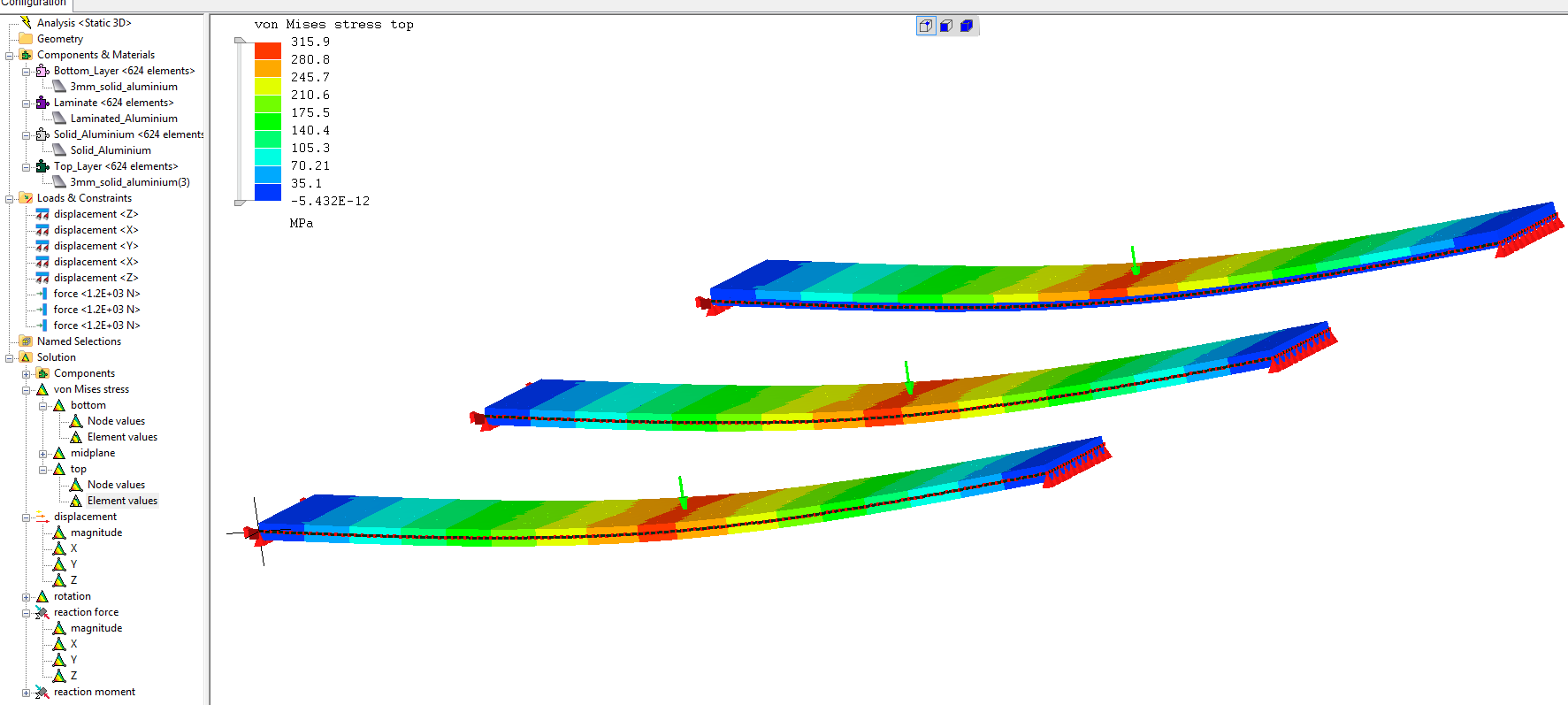
But when I select the "Top Element Values", I get the same stresses as seen in the last image.
All good then, the software works for these three methods.
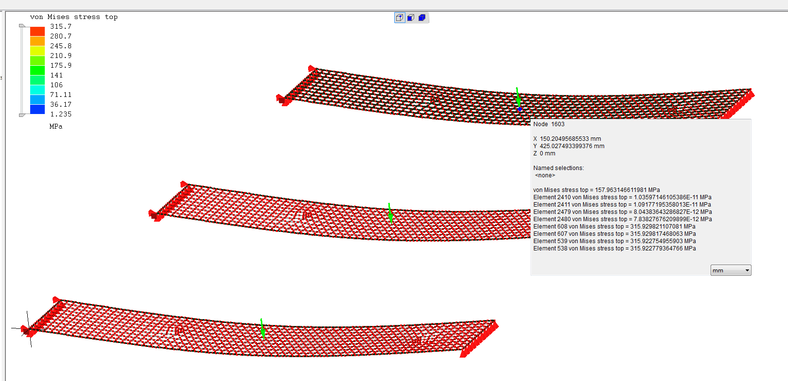
I also noticed that I get a warning "Elements 1873 and 1 overlap each other". I think these two elements are on the last beam where all the elements overlap each other. I don't know why I didn't get warnings for the rest of the overlapping elements?
My interest in all this is to gain confidence before venturing into analysing a fibreglass coated balsa structure.
1. Does anyone have a source of data for GRP (woven fibreglass cloth)?
2. Does anyone have suggestions for modelling fibreglass covered balsa structures? Is the laminate method using properties - thickness, angle, E1, E2, Nu12 etc acceptable or should I be using Orthotropic properties?


Howdy, Stranger!
It looks like you're new here. If you want to get involved, click one of these buttons!

Comments
The odd stress is because it's averaging the stress for all elements using that node - including the other layer. So yea, you have to use element values like you did.
Some warnings only show the first instance they find. I know it's not really ideal, it's just better than nothing.
Laminates with the internal solver aren't very good for sandwich type materials that have a very soft core. The CCX solver's laminates might perform better here, but solids are the gold standard. You might even use solids for the core (good for compression) and shells for the skin if that's easier to model than solids everywhere.
I don't have an answer for question 1. Hopefully someone will be able to help.
https://www.campusplastics.com/
I would use the laminate model for your balsa wood covered in fiberglass. The orthotropic shell is for one material. You could figure out what an equivalent property would be. But that takes special programs or testing. I believe there are also hand calcs you can do, if you have the right reference books. In any event, using the laminates saves you from having to do any of that. You also get to see what is failing. With the equivalent approach you have no detail.
Thanks for your suggestions. I will check them out.