Stuck?  support@mecway.com
support@mecway.com
Mecway
FEA
Tube Lifted on Slings using Contact

Hi
I am no FE analyst. I only occasionally do anything other than a basic linear static analysis to verify some hand calculations.
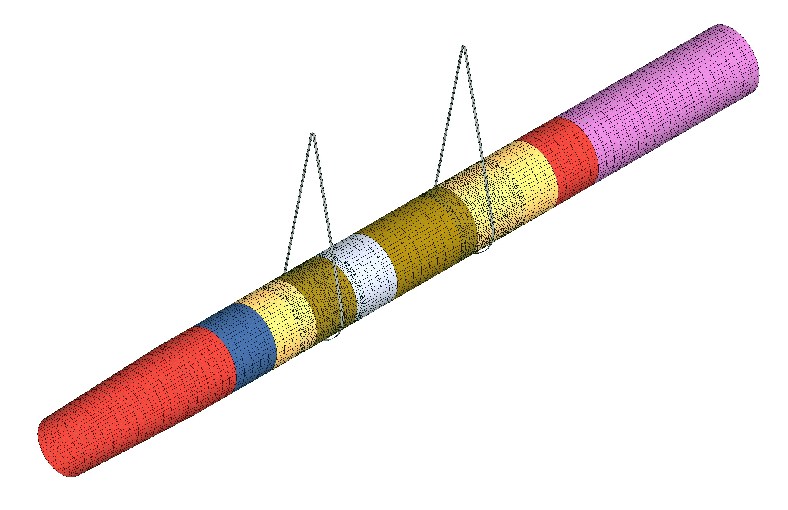
But I have ambitiously tried to model the lifting of a large tube using a pair of slings. See attached image.
As a start model I simply used a linear static model and used pressure to represent the sling contacts, having restrained the ends of the tube. This to get an idea of stress (see Model 1). It solves but it does not correctly reflect the actual contact pressure at the slings.
Then I tried the (some might say overly) ambitious route; using a non-linear static analysis in which I have attempted to displace the tube downward relative to the slings in an initial oversized state. See Model 2. I haven't got this to solve. I think my 2nd model will be pulled apart by anyone that knows FEA but please can anyone tell me whether:
1. I shouldn't be trying this kind of contact model (Model 2) with shells and I should start out with a solid model of the tube?
2. Whether the approach is just plain wrong from the get-go.
Thanks for any assistance
I am no FE analyst. I only occasionally do anything other than a basic linear static analysis to verify some hand calculations.
But I have ambitiously tried to model the lifting of a large tube using a pair of slings. See attached image.
As a start model I simply used a linear static model and used pressure to represent the sling contacts, having restrained the ends of the tube. This to get an idea of stress (see Model 1). It solves but it does not correctly reflect the actual contact pressure at the slings.
Then I tried the (some might say overly) ambitious route; using a non-linear static analysis in which I have attempted to displace the tube downward relative to the slings in an initial oversized state. See Model 2. I haven't got this to solve. I think my 2nd model will be pulled apart by anyone that knows FEA but please can anyone tell me whether:
1. I shouldn't be trying this kind of contact model (Model 2) with shells and I should start out with a solid model of the tube?
2. Whether the approach is just plain wrong from the get-go.
Thanks for any assistance
Howdy, Stranger!
It looks like you're new here. If you want to get involved, click one of these buttons!
Comments
This would be more oriented to see the stresses and strains of the pipe resting on a rigid saddle.
To evaluate the slings, you should include them on the model.
CCX shells can be finicky with rotational DOF constraints as well as some connections between shells where thickness or orientation change. These problems seem to be happening here - in particular, the multiple thicknesses appear to be causing CCX to exit abruptly. I would use solids (a single layer of hex20 elements) instead. You can join different thickness solid sections with bonded contact which is fairly robust in nonlinear large displacements with the Elastic option.
It's a good idea to begin with a coarse mesh, then refine it later. That way, you can get it working quicker and also check for mesh convergence. It's not always possible to un-refine a mesh without starting over and you may need coarser ones to compare to.
The elements are flat instead of curved. That will likely cause irregular stress and poor sliding at the contacts. It might have been caused by converting linear elements to quadratic. It's better to start with quadratic elements so they're remain curved through all the meshing operations.
There's no X constraint on the pipe so that may contribute to no solution.
Something strange is happening that I haven't been able to identify. Even with no contact, no slings, no rotational DOF constraints, single thickness, and automatic time stepping, I'm not getting it to displace more than about 1 mm.
By the way, this thing looks a lot like suction piles I used to analyze 20 years ago, check out page 43, you might find it interesting:
https://mdx2.plm.automation.siemens.com/sites/default/files/magazine/pdf/dynamics23_0.pdf
I'm just getting back to this today and taking all the comments on board. The common theme I take is, create the model using solids instead of shells. I've created a model with hex20 from the start, rather than my bad habit of starting with linear (for a quick run) and then converting to quadratic afterward, to avoid now the flat faces which should be curved. I'm time stepping gravity load instead of applying a displacement and moving the slings up to make initial contact with the tube from step 1. All excellent stuff so thank you all.
That said, I haven't yet managed to succeed in getting a sensible result. An analysis completes and the slings appear to deform correctly around the tube, but the tube itself is 'passing through' the slings and fails to deform/stress. It appears to be displacing as a rigid body under gravity. I will try to resolve any input errors further before re-posting, and maybe play around with contact stiffness a bit.
@JohnM this is a model of a monopile being lifted off the quayside for an offshore wind farm. An analysis is being done in another software package, with convergence difficulties of it's own. This is my parallel model that I wanted to do to satisfy myself whether the other analysis looks reasonable.
I remember those piles were fascinating. As big as a grain silo, getting unloaded from the ship was a major design issue, as well as the plunging event at the sea floor, the buckling while the ROV pumped out the water. I remember getting bi-phasic properties for the sand from a guy with a really thick Louisiana accent! Fun times. Good luck.
I halved it per Sergio's comment (cheers). Run time is still very long kicking off with small time step. I should have stayed with a simple constant wall thickness tube until behaviour was sensible and will revert to that again now.
I'm still not developing proper contact between sling and tube as can be seen in the screenshot. Maybe I need to start the initial sling with penetration into the tube all around the lower 180 degree circumference of the tube?
The sling displacements in the x direction seem extreme; I am expecting them to go taut but they seem to be wrapping over the tube. I have set their density very low in this version of the model but I don't think that should have a great effect? The tube is no longer passing vertically through the slings, using John M's suggestion (thanks once again) of using some elastic supports under the tube to kick off the analysis. They may still be over stiff and providing some support so I need to do some summing of reactions. I wonder whether I should temporarily support the slings similarly? But if anyone has any suggestions for next steps, they would be very welcome.
@ JohnM sounds like you don't do offshore work any more? Is the FE just for fun now? I can imagine those suction piles were a huge challenge but fun alright.
Beware though that it's only the normal displacements that should be equal. Where curved parts are sliding over each other, that displacement scaled up can be different for each part because the scaling is just linear and can't capture rotation. Not sure if this is significant here but it's a common issue when rotation occurs and ends up looking like a weird wrong distortion instead.
Sergio is right about the UY deflection - check the reaction FY force there, if it is significant, you are likely tipping and don't know it. I think you are okay on symmetry though, because you have the UX displacements at the cut, that covers it. I would remove the frictionless support on the straps, I don't think that is necessary.
By the way, FE has always been for fun, and often useful as well
Be patient, you are close to pushing past the painful part of the learning curve, and this stuff will start to pay real dividends!