Stuck?  support@mecway.com
support@mecway.com
Mecway
FEA
Bolt Assembly Example

Attached is an example of a bolt assembly. It is to show how to set boundary conditions and contact. I compared to a standard M16 Class 12.9 bolt and got great agreement with standard bolt calculators. I was not looking to analyze the bolt and nut thread stress. This is to load two plates and look at the bolt deflection and stress. The thread stress is already taken care of with standard bolt calculators. That is where the proof load comes from. So it's not to re-invent the wheel but to properly include them in your model when you need to.
Howdy, Stranger!
It looks like you're new here. If you want to get involved, click one of these buttons!
Comments
It took me several days but I finally got it updated. I have been running into persistent memory leaks and meshing problems with Mecway. If I mesh in Netgen and import the vol files, the meshing problems go away. The only way to deal with the memory leaks is to close Mecway and re-open it.
I did my best to size the geometry correctly. It is supposed to be a hex head M16 coarse pitch 2mm, 50mm full thread bolt. I looked around the internet trying to find dimensions and properties etc. The original model I was trying to get the same bolt and nut but with a fine pitch. I noticed some of the specs only seem to be available for coarse thread. I think I had mismatched specs before. That's solved now.
For some reason, the online bolt calculators and what I see with FEA are very different. For just the bolt, not in an assembly, there is a factor of 3 difference between FEA and the online calculators. With the assembly, there is a factor of 8 difference. These factors constantly shift as well. It depends on the geometry, the mesh, material properties etc... I sized the preload and tightening torque based off the FEA models.
The example is meant to show how to setup contact so that you get the twisting and the tension in a realistic manner. I wasn't trying to re-engineer the bolt and nut. Moreover, the threads where purposefully left out.
The original model was a much higher resolution. This model was intended to be coarse. I replaced fillets with chamfers to save mesh density.
I gave up with trying to get the contact to look better. It is splotchy in places. I tried over and over, but this is the best I could do. You may have better luck with it.
Contact and cyclic symmetry are both so much easier and faster in ANSYS. This type of analysis isn't well suited for Mecway and CCX, in their current state. This is around an hour to do in ANSYS. I spent several days on it and still not really happy with it.
I added a lot more information and files to the download, to make it easier to follow.
updates below
I have attached a Mecway model of pret1.inp from the CCX verifsamples. It is essentially the original pretension section command first developed by ABAQUS in the 90's (which is what gained them all of the automotive market share). It works, but it's not easy to implement. I have found the thermal prestress trick to be good enough for our purposes, but if we did a lot of bolt assessments, I might be tempted to build on pret1.inp.
I have a very different experience with contact. When there is "splotch" in the results, it is often the result of large variation in mesh size / insufficient density. I used ANSYS for decades and got used to that mid-side node "overshoot" in contact patterns. Commercial codes now often mask this effect with postprocessing - it's real, they just hide it.
I'll take a look. I am definitely being limited by mesh density. I tried numerous models before I arrived at the one with chamfers. That's about the best my computer can deal with.
I experimented with contact stiffness last night and got results similar to the first model. Where you have the nice stress and displacement detail. About '1e6 GPa/m' for the 'Contact' pairs seems to work good. The default Mecway was giving was '2000 GPa/m'. The first model had increased inputs for those values too.
Instead of the 'Tie' option for the 'Bonded Contact' pairs I'm going to experiment with the 'Elastic' option and see if that helps with the splotchyness.
I've never tried to compare to the bolt calculators before. Given how long bolts and tightening torque tables have been around, I have to believe those are the numbers people use most of the time. I'm not yet sure why I'm so far off. I may be missing something there.
One nice thing with the actual Netgen program is it has element quality plots. Each part meshed very fast and with a good quality. So I at least no there shouldn't be an issue there. It would be better to use fillets instead of chamfers though. I had to make that compromise.
Something is going horribly wrong with Mecway's inbuilt Netgen, both the 'Netgen' and 'Netgen 6' options. It's having real problems generating meshes. I've lost days many times due to bad meshes. When I tried with standalone Netgen all the problems went away.
There are a lot more contact pairs though. So run times go from 2.59 to 7.47 on my computer.
It's hard to see how the online calculators can be that accurate. Just changing the plate materials drastically changes the bolt, washer, and nut stress. Other significant changes come from material properties and boundary conditions. So a simple proof load and tightening torque calculation seems hard to believe right now.
Updates below
Updates below
Wow, after further study, this is pretty crazy. This is a great use of FEA. Only a rod will match the bolt calculators. Changes in BC change the results a lot. If you model the head of the bolt, like I have, then the results change dramatically. The stress seems to go up because the head of the bolt is not infinitely rigid. Also, how the BC changes things too.
So I did even more tests and what I'm seeing is very consistent with the topic of fillet concentration factors. Various setups I've seen 3-8x more stress than in the shank of the bolt. The online calculators seem to be referring to the shank only.
It doesn't seem like the torque tightening specifications take into account the fillet stress concentration. Some of the calculators try to account for the type of joint. However, I definitely prefer the FEA approach. You can really see what's going on.
I've never worked with torque specs for bolts before. I don't know if anyone has any insights.
I also made higher mesh density models and the splotchyness was not present at 1e5, 1e6, and 2e6. Based on all the testing; using chamfers, 1e6 GPa/m, and a good quality mesh should work well. Unfortunately, the attached model has a little bit lower quality mesh. I was trying to get the mesh as small as possible. The high number of contact elements, 200-300k, is what's slowing this particular model down.
I'm confused as to why the online bolt calculators work from the stress in the shank of the bolt, rather than the peak stress in the fillets.
Updates below
so if you are trying to analyze the bolt stress, you really need a good dimension reference. i couldn't find anything too good. but this is working and still shows how to setup the contact.
as with before, i used 1e6 GPa/m for all contact stiffness values. the min mesh size was .4mm, which is the chamfer size i put on the parts to avoid re-entrant corners. i meshed in netgen and imported the *.vol files. the mecway built in version is having problems. this makes setting up everything a lot harder, but at least it works.
the large number of elastic contact pairs is what slows the solve down and makes for a good benchmark, as others have found. so this model can still be used to benchmark. on my crappy laptop it solves in 10 mins 32secs with two cores. i'm using the intel mkl pardiso ccx non-linear solver.
so the online bolt calculators are fine. i figured they would have to be. bolts and threads have been around forever. the critical dimension is the bolt head fillet. i used chamfers to save mesh size. i can't solve large models on this computer.
updates below
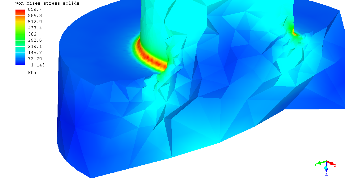
note; based on the stress results, a grade 4.6 bolt would be best. you could load that to .75% of it's proof load and the aluminum plate and stainless steel washers wouldn't be over stressed. the highest stressed part is the washer at the bolt head. the next highest stressed part is the aluminum plate. i ran stress on just the plates and the results are significantly different than running the whole assembly. it's best to run the whole assembly, since the plate and washers get more realistic loading. running just the plates is 10x faster though. the final loads i used were 46kN for the axial force and 146Nm for the torque. i made a torque calculator to relate the force and torque, using the same formulas as the online calculators. i changed all the contact stiffness values to 1e5 GPa/m as well. to run the plates by themselves, i split the surfaces where the washers contact the plates. those models aren't in the download.
Edit:
Someone once asked for the CCX inp files of this example. So I added them to the download. I noticed that I didn't update something in the spreadsheet that I meant to. I fixed that now. This was the note on max number of equations. It seems to be about 22 million for 16gb of memory. I added a pdf version of the spreadsheet, in case you can't open the spreadsheet. I also added sub folders, to make it easier to find things of interest.
P.S.:
I should probably say that the part dimensions are different for each of the updates. The original post had a CAD issue. I thought I was entering diameter values, but they were radius values. So the original upload is way off from what I intended. Update 2 fixed that. There was a question as to the bolt fillet head radius. I went with 2mm as that gave more of a contact patch. However, the actual value is said to be 3mm. So in Update 3, I used the 3mm value. This decreases the contact area and causes a much higher stress to form in a different location. Update 3 seems to match the standard bolt calculators really well, if you look at the first thread bolt stress, near the top of the nut. The FEA model shows the bolt head fillet stress is much higher than that though. The stress, in the contact area of the bolt head, is the highest. This seems like a reentrant corner to me. However, all the drawings I have seen seem to have this. All the parts are well within their allowables though. The FEA model was useful for showing that to connect an aluminum plate to a stainless steel plate, you would want to use a Grade 4.6 bolt. Otherwise, the aluminum plate will get crushed and fail. I spent a lot of time experimenting with the contact setup. This was the best I could come up with. It isn't too different from previous models. I applied the bolt torque differently this time. This was to get the motion I was looking for out of the bolt. All the parts are moving the way I want them to. If you look closely, you will see the bolt and nut turning in the correct directions. Also, the bolt elongates and the nut moves in the opposite direction.
This version of Mecway does a worse job of showing the cut plane. There is some sort of reflection that wasn't in older versions. This makes the cut plane view look a lot worse. So I didn't make animations of this version. I just saved some images.
This time around, PASTIX was faster than PARDISO. These are my benchmark results:
Computer Type; Low cost laptop
CPU; Intel Core i5-1135G7
RAM; 16GB LPDDR4
CCX set to use four cores
Intel MKL PARDISO Solver; 10 mins 11 sec
PASTIX Solver; 8 mins 54 sec (12.6% faster)
The ssd is about 11x less bandwidth than most computers. The memory is about 3x less bandwidth than most computers.
The times I use are from the Mecway output window, after it has finished processing the results. You will notice the CCX run times are not the same. Also, the Mecway time will change. To match what I have shown, wait for it to completely finish.
The run times vary a lot on my computer. I sometimes saw an over 30% speedup using PASTIX. You would have to do a lot of runs and take an average of each, to get a better idea. I didn't want to spend that much time doing that though, as I didn't want to stress my laptop that much.
At one point, during a PASTIX run, the solver caused my computer to reboot mid solve. This happened with a higher node count. PARDISO just goes to out of core. Then I have to manually kill the process, because it gets way to slow. Victor has mentioned you may need to apply a patch to get out of core working with PARDISO.
this is a cut plane view, so there are missing elements that cause some jaggedness.
6:31 PASTIX Intel i7-10700 2.99Ghz 32GB using 6 proc
00:09:18 PardisoMKL OOC
00:05:16 Pastix
“I'm confused as to why the online bolt calculators work from the stress in the shank of the bolt, rather than the peak stress in the fillets.”
It’s due to the typical failure modes of bolts. Most bolts are fairly ductile, so some yielding at the fillet at the head is acceptable. Most bolts fail in net section tension (external force is greater the ultimate strength of the cross section of the shank) or fatigue at the first thread in the nut/threaded part (high fatigue notch factor - stress concentration).
A properly torqued bolt sees very little of the external load, as most of the external tensile load is used to reduce compression in the clamped members. Therefore, fluctuating external loads have little effect on creating an alternating stress in the fillet at the head, which is less severe than in the thread, and subsequently bolts rarely exhibit in-service fatigue failures at the fillet.
For fatigue evaluations, the peak stress at the first thread is usually determined by multiplying the calculated stress in the shank by an empirically derived factor of 3-4, depending on how the threads are formed.
Hope this helps!
thanks. bolts are rather interesting. the fact that they are installed near their failure point had made me wonder why they don't break as soon as an external load is applied. you're explanation makes sense.