Stuck?  support@mecway.com
support@mecway.com
Mecway
FEA
NL Static 3D - Bolt Connection with Preload

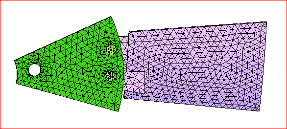
A blade and segment of a center disk are assembled using bolts connection as shown below. The objective to this analysis is to predict stresses around the blade holes.
A non-linear 3D static solution is obtained without any errors but Von mises stresses are missing due to non-converged solution. Per Victor's suggestion, I have added weak springs to eliminate the rigid body motion. This didn't solve the issue.
looking for recommendations on how to approach this problem? will adding bolt preload resolve the issue? If so, how do we apply it in Mecway/CCX?
I need to predict stresses around the blade holes.
Thank you in advance.
Howdy, Stranger!
It looks like you're new here. If you want to get involved, click one of these buttons!
Comments
I’m not an expert in Mecway to add thermal expansion coefficient to the bolts. Do you have a sample or link on how to do this?
Thanks
Just to make sure I understand your approach. First I should assign thermal expansion coefficient in the material properties for bolts only and then select the nodes on the bolts and assign temperature under New Loads and Constraints. Is this correct? Should I apply thermal concept to the bolts only or nuts as well?
prop_design,
I am interested in the stress values at the cylindrical surface of the blade holes. Fixing washer size surfaces on the blade flat surface will generate high localized stresses in the region...I will give it a try tho. And you're absolutely correct about the C.G. of the assembly being offset. It's only a generic model I created to show the problem.
Thanks and appreciate you both. Will give it a try.
also if you use cad to make the washer face cutouts in the surface you can get nice round surfaces to fix in the cad view of mecway. that makes it so you can remesh without having to redefine the boundary conditions. they will also be smooth too. doing it from the mesh makes them lumpy.
* updated in later post
1. I am trying to model/analyze a bolt connect assembly to predict stresses around the blade holes. In your simplified version you have removed all the bolts/nuts and that's representative of my model. Can you suggest a solution to my original model with bolts and nots and contacts?
2. As I mentioned earlier, this is a generic model of the blade assembled to the center disk by virtue of bolts/nuts. The actual plastic part does have fillets and design properly.
Thank you again,
* updated in later post
thinking on your model. i'm confused as to why you wouldn't be looking at the nylon part. the other parts were steel. so the blade is what would fail. the way i modeled it in the example should be loading the blade right. i don't think you need all the complicated bolts, hub, etc... but i may not be understanding what you are trying to do.
the free version of ansys is here; https://www.ansys.com/academic
there are a lot of products with it. i always used the workbench environment and it has a lot of great things. but a lot of frustrating things too. so that is why i switched to mecway. if you never used it, it may be too difficult to figure out how to use. if you know how to use it, it's very easy and fast to do most things. other things impossible. mecway makes a lot of those impossible things very easy. for me, mecway was a better choice as i only need to look at the blades and not the retentions. for retentions ansys workbench is a lot better. i have to be honest. even though it's a mecway forum. sorry
here are some comparisons with a bolt preload force and cyclic symmetry. if i tried to apply the preload moment it errored out.
i'm also attaching the updated model but i cleared the solutions to shrink the file size. configurations 1 and 3 are the most significant. four would be ideal but won't run. two was a test.
* updated in later post
How did you add fillets to the model? Did you FreeCad software?
Thanks
moi is here; http://moi3d.com/
i updated the cad model fillets. i was able to get rid of the sharp point in my first model. this is much better from a safety and manufacturing point of view. everything about the mecway model is the same. i just updated the geometry and mesh and re-solved. all the pics are for the updated model. i attached the updated model as well. hope this helps. i believe it addresses the stress in the nylon blade holes, like you wanted.
i cleared the results to save file size. just re-solve each config. config 1 is what i would do if it was me. config 3 is more like what you are going for. config 4 would be ideal but errors out. config 2 was a test i did.
anthony
ok i think i got what you want. i modified your contact setup based on the experiments i did with a test model. i can't say for sure if it's right as i'm not a mecway expert. but it converges and looks pretty cool.
* updated model in a later post
I've struggled with this problem and can't work out why it won't work with only contact (no fixed supports or bonded contacts holding the bolts onto the plates). Some things I tried that failed:
These things did help but likely aren't satisfactory:
I'm a bit wondering about the suitability of a single FEA model for this problem though. The bolts seem to be loose which makes me think the stress could be sensitive to the size of the clearances between the various surfaces.
Great job. Your latest approach is more realistic than ones suggested earlier and the results seem to make sense as well. Great work!
Hooshsim
i was starting to add more detailed BCs to the bolts and noticed your fixed BC was not right. you had some of the blot/nut faces fixed. this greatly changes the results since the cg of the assembly is off axis. i will post and update soon. i also have some added configs with extra layers of detail to the BCs
i attached an updated model. there are additional configurations. i noticed your fixed support didn't seem right. i tried to correct it the best i could. however, there doesn't seem to be geometry showing what fixes it in the z axis. in config three i selected some faces in that regard. but i would cut the surface wherever it is fixed in z so you can select it. instead of fixing the hole in all directions i would set the displacement to zero for xy. it can't be fixed in z from the inside of the hole as it is now. since the cg is off axis from the xy plane there is a substantial amount of stress and displacement compared to how you had it fixed.
i added some forces and moments to the bolts. they show what i would do but i don't know the magnitudes for the size bolts. you would have to do some calcs to find those out. i tried various values to keep the stress within reason.
so something along the lines of config 3 is where i would start. i would work on the fixed restraint like i said. i would also fillet the blade and the bolt if it were me.
you will probably have to experiment with the stiffness of the contact inputs. if you use ansys or something similar you will probably get better results.
but that's about the best i can do with it. the attached model has the results cleared to save file size. just re-solve each config. the first two solve in six iterations. the third config takes seven.
here is an update with perhaps better BCs. i noticed you didn't have the shank bonded to the nut. so i added that. i also changed how the forces and moments are applied. i changed the contact stiffness values. i changed the fixed displacement conditions. i experimented with the contact. what is attached is the best i can come up with.
as i mentioned before the shank shouldn't be in contact with your cd plate or the blade plate. it won't run unless i bond them. i would make the diameter of the two plates slightly bigger than the shank. it looks like you have a m10 bolt. so if you look for the fillet radius of that bolt, that is what the plate holes should align to. i used the min force and moment for the m10 bolt in config two.
i realized that the cd plate is moving a lot and the bolts are dense. i was thinking of a typical propeller where the retention is very stiff and only the blade is moving. in your model you do need the bolts in there for the density aspect. i don't know if you wanted the preload effect from the bolts. so i was trying to add that in case you did. this time i moved the force and moments to the plates figuring you weren't interested in the bolts. if you want to have the bolts accurate you would have to do a bit different setup. i have been working on it in mecway for an example bolt and it's a nightmare. so i would definitely recommend something better at contact if you want to get into the bolt aspect more.
just re-solve the attached model. i don't have the geometry files so i had to apply the loads and restraints to the mesh faces. you can do this better since you have the geometry files. i'm not sure what is restraining it in z so i just guess at that.
In this cases I like to work with multiple steps, first for bolt preloading and the second for the main loading (centrifugal acceleration in this case). As in Mecway that possibility doesn´t exist, what I did was change the time to 2, and use time 0 to 1 for bolt preloading and 1 to 2 for main loading, getting the same results using tables for loadings.
I include a thermal restrain in the bolts to create the pretension (70-85% of the bolt yield stress), and then the centrifugal acceleration. Have to add manually the cyclic simmetric boundary condition. For the blade acceleration have used 900 RPMs (would be nice to have RPM in the GUI directly).
In the X-Y plots what we see is the stress in the bolt shank, about 700 MPa for an 10.9 bolt. With more time what I do is divide the flanks of the bolt to apply restrain only in that portion and not in the head or thread that should not deform, but still in my humild opinion results are enough accurate for the matter.
This is great work. Thank you!
I resolved the convergence issue by Replacing “contact” to “bonded contact” for bolt head in my original model.
Thanks to all for sharing and contributing your support, specially Victor.