Stuck?  support@mecway.com
support@mecway.com
Mecway
FEA
Distributing (RBE3) node-surface coupling
Hi
I'm modeling and analyzing the chassis of a car and have applied some point masses but also have such things as the bodywork, which I need to distribute the weight of across the whole car.
I assume that the bodywork has no stiffness because modeling it would add significant work.
I currently have put 1 mass for the bodywork and put a node-surface coupling with distributing (RBE3) behavior which connects to all of the tubes that the bodywork is connected to, but now I'm doubting if that really behaves as I intend to. The doubt comes from me not knowing how the weighting factors that determine how the forces are distributed are calculated.
Does this account for the stiffness of the structure so the load goes mostly to the parts that are closest to the boundary conditions or are the weighting factors just based on the distance?
I think it does not put weighting factors based on the stiffness, but I would appreciate if any of you know anything for certain.
Howdy, Stranger!
It looks like you're new here. If you want to get involved, click one of these buttons!
Comments
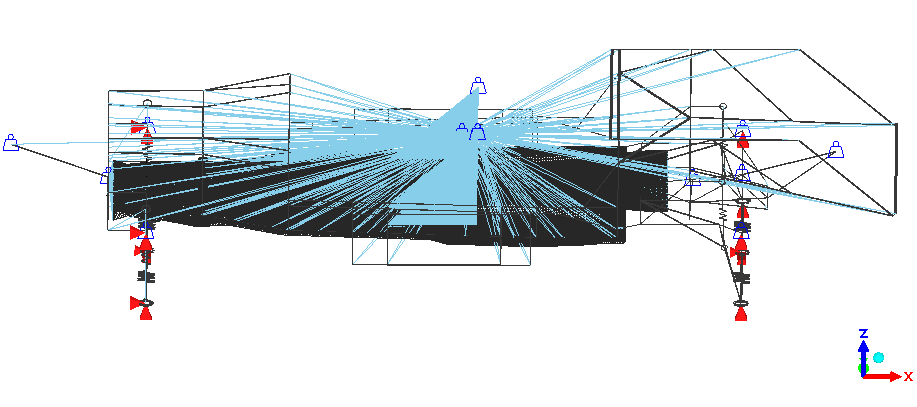
The solution with *Coupling + *Distributing depends on the position of the reference node.
This is because the solution must be statically compatible with the applied load. If the load is only a weight —for example, (F_z)— and the reference node is not located at the CG of the SURFACE, CalculiX will add (F_z) forces to the nodes.
By the way, I think this is only handled correctly by the solver for flat surfaces.
This means that the weights are proportional to the area, I agree, but the force —which I assume is what you are interested in, is also affected by the ref node lever arm to each surface.
In this case, the position of the reference node is especially important because, from my point of view, neither the human body nor a belt can transfer moment to the chassis. The body is not connected to the chassis and the belt has no rotational stiffness.
@disla I do intend for moments to be transferred as I have put the masses in the estimated center of mass positions. As for whether a human body can transfer moments, I would say that it can until a point as the lower back, butt and legs contact over an area, so the contact force is something like a force + a moment to account for the reaction force moving a bit. Laterally, the seat has support up to about shoulder height, so that is above the height of the body center of gravity and thus this will transfer the moment to the seat mounting bars. To constrain the body, I have a bit more work to do with the tension-only members as the belts will obviously be tension-only members and will be connected to nodes that are only bound to the longitudinal displacement of the body mass node. To have the seat support rearwards longitudinal displacements to fully constrain the body, I'll have to use some tension-only members in front of the body, connected to the seat behind it.
So to sum up the support of the degree of freedom of the body: Longitudinal forwards displacement is taken by the seatbelts, Longitudinal rearwards displacement is taken by the seat and vertical displacement is taken by the seat (both ways because the loads will only pull it down). A Rotation about the longitudinal axis is supported by the seat, rotation about the lateral axis is supported in part by seatbelts and by the seat and rotation about the vertical axis will be constrained artificially as it is not of interest for this analysis.
I would make a small distinction. Human Body can "induce" moment (by means of an offset force) but *distributing solve the static compatibility by means of a Force couple. Check the example. An offset in the Ref node generates traction in the oposite side of the distributing SURFACE. A human body resting on a seat won't do that. That's what I mean.
I guess I could use more tension-only members to make it so that the body would only apply the lateral force as a contact on one side of the seat, but then I would need to model the seat in more detail too for this to have any value.
Regards
But yeah, when we are building race cars, finding realistic load cases with as little analysis as possible is always quite tricky. On those cars, we have the predictable loads being the forces due to the tyre contact forces and then we have a bunch of unpredictable loads due to the drivers going agressively on a kerb, them hitting or pushing each other with their cars or them going off the track and stopping in the sand pits. Then we need to control that nothing on the car breaks during racing but that in an overloading/crash scenario it should preferably be an inexpensive and easily replaceable component that bends or breaks while leaving the large machined parts intact.
For example, I recently had to design mounting brackets for a front wing that would not fail easily or have fatigue issues but would absolutely fail before damaging the aluminum crashbox that it was attached to (see the thread about OpenRadioss simulations for that part) and the front wing should preferably just come partially loose without being damaged beyond repair. That was a tricky task with many opposing objectives as the bracket should at the same time not add too much stiffness to the crashbox as the crash behavior of that part could not change too much because of it either.