Stuck?  support@mecway.com
support@mecway.com
Mecway
FEA
Convergence Issue with Concrete (Linear Compression) and Steel Interface

Hi there, i got convergence issues, with my Tubular joint model comprised of steel tubulars with grout infills. The grout is linear compression material as per below.
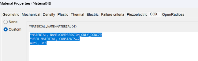
There is a bonded contact defined between the grout and the steel tubes. Since the grout carries compression only, no tensile forces are transferred through the grout to the inner tube. I have node surface couplings as well for load application, all bad things are here to avoid the convergence, any ideas. Would it be better to model the grout as a plastic material with a defined stress–strain curve, and then replace the bonded interface with a unilateral (compression-only) contact between the steel and grout? My thought is that this would ensure the grout remains in compression and may help stabilize the solution. Not ideal as concrete can behave like von mises stresses, but in our case, they will always be subjected to compression?
Use below link to access the mecway file. anyone can open a link, you don't need dropbox account. size is 78MB.
https://www.dropbox.com/t/F2AL29yupRrZJBAo
Howdy, Stranger!
It looks like you're new here. If you want to get involved, click one of these buttons!
Comments
I have not tried it yet but Radioss may work better, for one thing, I think it has a better concrete model available.
Actual behavior is not a fixed tensile strength, but one that is larger and larger as the element under consideration gets smaller. Actual behavior has the tension vector rotating as the concrete fails in tension, putting compression across the crack, and the concrete expanding (poisson ratio > .19). In your case this expansion can cause the tube to restrain the expansion putting a confining compression on the concrete. Increasing the tensile strength limit up to about 14 Mpa can arrest this unziping in shear behavior, but the issue is more that the lack of variable poissons ratio, the sudden kink in behavior of the concrete, and the lack of an accurate shear model make composite/steel plastic behavior unable to be modeled with the compression only concrete model, which does not even include poissons ratio...
I’ve been dealing with a bit of a conundrum, as several of these challenging issues seem to be present in my case. I was exploring an alternative approach by defining contact between the concrete and both the sleeve and the pile, with the idea that the concrete would remain primarily under compression. In this setup, no direct tensile load would be applied from either the pile or the main leg acting as the sleeve.
This would allow me to define the concrete using plastic material properties. I realize this may be somewhat of a simplification, since it essentially treats the concrete response more like a von Mises-type behavior, which is not truly representative of concrete’s directional characteristics. However, since the concrete is externally confined and mainly subjected to compression, it seemed like a reasonable approximation — although the internal stress state under loading is still an open question.
That said, I’ve been struggling with convergence when modeling the contact interaction between the plastic concrete and the steel components, so it’s not an ideal solution. I may look into trying the OpenRadioss solver as an alternative.
I hope you’re well.
I’ve managed to run several analyses to convergence — some using compression-only concrete, and others using a Mohr-Coulomb model. In these models, I defined gap elements between the sleeve and the concrete, and between the concrete and the pile.
I’ve also created another version using contact with a small tangential stiffness, allowing a small amount of slip in case the concrete needs to “breathe.”
One strange observation is that all the models seem to stop converging around the 0.17–0.18 mark. I have scaled the loads by a factor of five, so 0.2t represents the full design load. As you know, the joint was already struggling under the classical API joint check approach, which is why I moved to nonlinear analysis.
I’ve attached a few example cases for your review. The models are quite large, so I’ve included a download link instead.
I would appreciate it if you could take a look and let me know whether the approach and results seem reasonable.
https://www.dropbox.com/t/UQ3ibRoDO5eMzggN
I.e. I think your problem is on the bleeding edge, but with appropriate modeling you may get somewhere, but full composite behavior will require work on how you model the interface and concrete, and possible modification of your section (roughening, dimpling, internal ribs, expansive concrete... etc.). Note rebar have ribs, the configuration of which was developed over about a century to get well behaved composite behavior. Concrete shear is another similar problem. Explicit modeling with a penalty model is usually used (see RaDIOSS OR lsDYNA), but the parameters usually need to be chosen from what fits test data rather than code recommended values.
https://maps.app.goo.gl/k7rnooejCvnYWaxC7
Picture of a crash barrier to deal with overheight trucks before they hit fuel line on the RR bridge a hundred yeads further on. Triangular high strength thick wall steel tube filled with concrete. Not designed composite, but probably is at least partially.
Thank you for your valuable insight. I was able to run the compression-only material model and obtained reasonable results, whereas the other model failed to converge.
I understand that both API RP 2A and ISO 19902 address grouted joints and double-skin tubular members where the annulus is filled with grout (concrete). I have therefore adopted those provisions for the time being.
Perhaps in the future I may attempt to develop a more robust numerical model; however, given the current challenges associated with modelling concrete behaviour and the reluctance of CalculiX to handle it effectively, this seems to be the most practical approach for now.