Stuck?  support@mecway.com
support@mecway.com
Mecway
FEA
Sail rigging analysis

Hello,
I am performing analysis for a square-rigged sailing rig, which I have modeled as follows:
Initially I assigned all elements representing ropes as Tension only truss elements. However, the internal static 3D solver would not converge, I expect due to large displacements.
I then tried nonlinear analysis using CCX solver. To do so I had to turn off the tension only selection for the ropes. I have been unable to achieve convergence with this approach either.
Any advice how to go about this? Perhaps I need to pretension the rigging elements, or try load ramping? Thanks for any recommendations you may have.
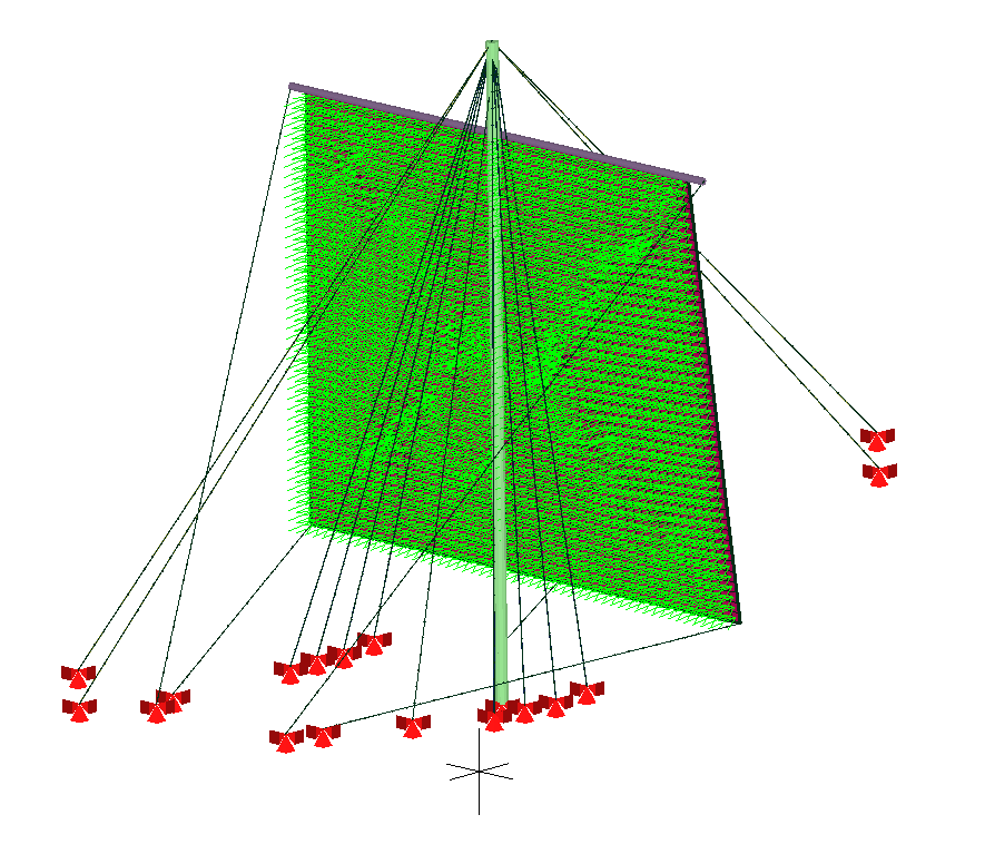
Here are images of the model with & without loads/BC's:
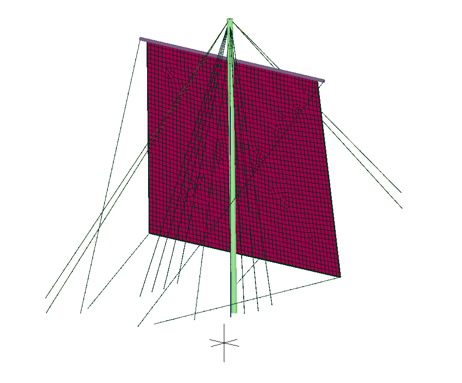
I am performing analysis for a square-rigged sailing rig, which I have modeled as follows:
- Sail canvas modeled as isotropic shell/membrane elements, 0.039" thick
- The edges of the sail are reinforced with rope, which is modeled as beam elements, which have nodes common with the perimeter edges of the sail's shell elements (these were co-located and have been merged)
- Wooden mast and yardarm modeled as beam elements
- Stays & shrouds (ropes) supporting the mast are modeled as beam elements
- Sail handling lines (also ropes) modeled as beam elements
- Displacement xyz constraints applied at the mast step (base of mast), and where the standing and running rigging are secured
- Uniform pressure applied to the sail
- Gravity applied
Initially I assigned all elements representing ropes as Tension only truss elements. However, the internal static 3D solver would not converge, I expect due to large displacements.
I then tried nonlinear analysis using CCX solver. To do so I had to turn off the tension only selection for the ropes. I have been unable to achieve convergence with this approach either.
Any advice how to go about this? Perhaps I need to pretension the rigging elements, or try load ramping? Thanks for any recommendations you may have.
Here are images of the model with & without loads/BC's:
Howdy, Stranger!
It looks like you're new here. If you want to get involved, click one of these buttons!
Comments
-start simple, make that work first (in this case perhaps set up the mast alone with a simple concentrated load and get that to work b4 adding the complexity of the sail
-get the static linear model to solve first, if u can't get that to solve then there is little chance of getting the non-linear analysis to work.
-I avoid using beams as rigging elements (unless I'm applying a UDL type load to them), I use truss elements where possible. Particularly in the non-linear analysis they have tendency to spin around there own axis and require more constraints to converge on a solution.
-be careful when using shells in non-linear analysis, if they have any node-surface connections I normally have problems
-I have had little to no luck with tension only elements. The simplest approach i have is to run the analysis, they simply remove any rigging element that is in compression or apply a very elastic material property to it. I have developed my own methods of dealing with rigging elements in tension -I split the truss element in 2 and apply a small side load - if it goes into compression the small side load is enough to cause it to 'buckle' and often allows the solution to converge. Other approaches I have had some success is by prebending the rigging element again allowing it to buckle but this often requires something to stabilise it before convergence will be permitted.
-I apply pretension by either moving the mast foot up before the loads are applied (as how it is done in the real world) or by shrinking the appropriate rigging elements by cooling them down.
if u post u file I'm happy to take a quick look -and good luck!
File attached, let me know if you have any feedback.