Problem Incompatible constraints on nodes when performing DC Crrent Flow analysis Version 24 / 21
Hello
I am facing a problem during performing a DC current flow analysis with Mecway solver.
When I start solver, I get solver error message right in the beginning
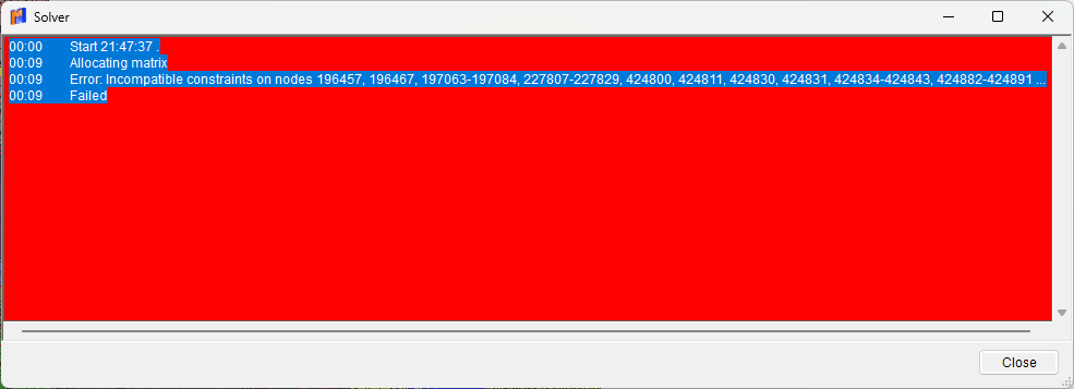
"Error: Incompatible constraints on nodes 196457, 196467, 197063-197084, 227807-227829, 424800, 424811, 42483..."

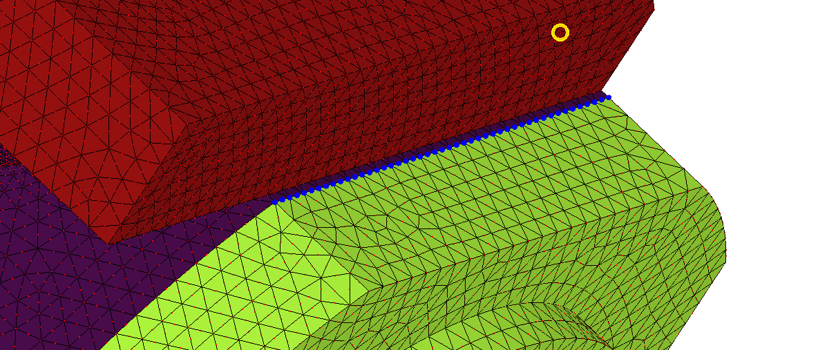
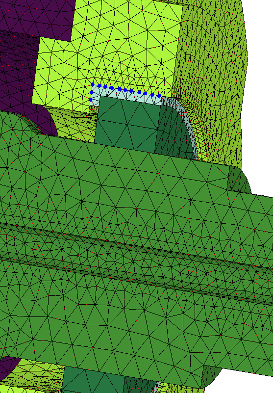
The nodes involved seem to be on faces and edges where I used bonded contact.
here the nodes are on the dark blue part

here they are on the upper green part

Does any one have an idea to get rid of the errors.
Regards
I am facing a problem during performing a DC current flow analysis with Mecway solver.
When I start solver, I get solver error message right in the beginning
"Error: Incompatible constraints on nodes 196457, 196467, 197063-197084, 227807-227829, 424800, 424811, 42483..."

The nodes involved seem to be on faces and edges where I used bonded contact.
here the nodes are on the dark blue part

here they are on the upper green part

Does any one have an idea to get rid of the errors.
Regards
Howdy, Stranger!
It looks like you're new here. If you want to get involved, click one of these buttons!

Comments
How many nodes can be handled by the internal solver for DC current flow calculations?
Regards
You can also avoid it by consolidating multiple bonded contacts if possible.
Version 26 is less restrictive here and allows slave nodes to also be master nodes of other bonded contacts so you can avoid the problem in some cases by swapping master/slave surfaces.
The maximum number of nodes for DC current will be greater than static and similar to thermal steady state because its 1 DOF per node. So maybe a couple of million, at a guess.
thank you for your answer. I was able to solve the problem. In the case of picture 2 swapping master/slave surfaces was agood Idea. 3rd picture, I found it was my mistake, because i had a double definition of a contact.
Thank you also for your information about symmetry boundary in connection with DC curent flow.
One more question about node internal heat generation using "Transfer internal heat generation from solution". Is ther any option to calculate the total amount of heat generated in a volume of a part. (Imported values from solution are node values)
Regards
I am struggling again with an error message of the Mecway-Solver
It says Error: Element 268788 has incorrect topology. It may be inverted, tangled, flattened or severely distorted. (DC current analysis worked fine without issues) .
When I transfered internal heat generation from solution and make a therm. steady state calculation i'll gett that error. What can I do? How to correct the element? Deleting it did not help, another one popped up.
Regards
I solved the problem doing a remeshing with modified meshing parameters.
But I was only able to find those elements by the searching with element number, didn't see a red "X"