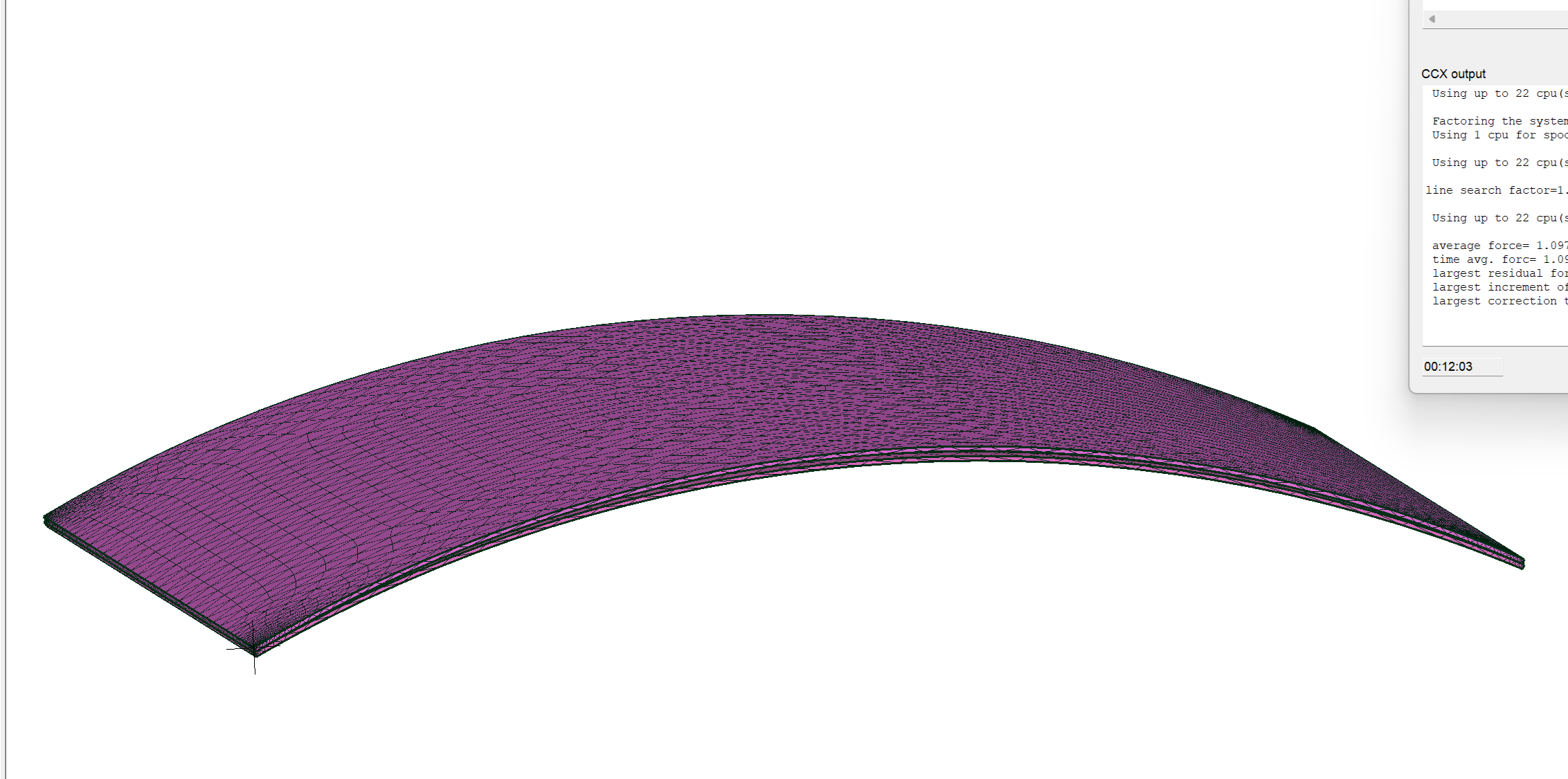
How can I model an imposed deformation
In this situation, I have a mold and a glass that is almost the correct size for the mold. I would like to deform the top plate (glass) so that it assumes the position of the mold and then analyze the stress response.
Although the gap in the file is 3mm, I need the glass to take the shape of the mold.
The contact stiffness is just a test for the glass to slide over the mold.
Could you give me a tip on how I can do this analysis?
Although the gap in the file is 3mm, I need the glass to take the shape of the mold.
The contact stiffness is just a test for the glass to slide over the mold.
Could you give me a tip on how I can do this analysis?

Howdy, Stranger!
It looks like you're new here. If you want to get involved, click one of these buttons!

Comments
For example. If glass assembles on top of the mold in horizontal position, self-weight seems enough to make glass and mold to accommodate each other, and it could represent a natural way to solve the problem without the need to impose artificial displacements.
By other hand I would work on the mesh to get a cleaner and structured pattern in thickness direction. Minimum three or four elements in depth.
Friction complicates things and can generate peak stresses at the corners.
EDITED: Initial gap seems more than 3mm