Is it possible to mesh truss elements?
I'm following the Truss tutorial on the Optional module of the course "A Hands-on Introduction to Engineering Simulations" of EDX
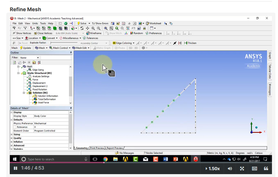
There, I saw that a simple truss structure, composed of 3 elements, was refined into 30 elements:

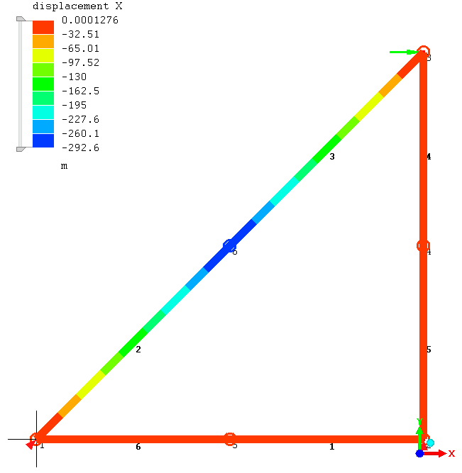
I tried doing the same with Mecway, but even with only a 2x refinement, I'm getting huge displacements in the blue region:

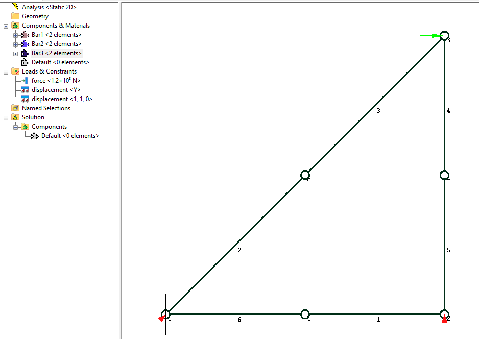
My model looks like this:

It's constrained in the bottom left corner in the x and y directions, it's constrained in the y direction in the bottom right corner and a horizontal force is being applied in the top left corner.
What am I doing wrong?
Thank you,
Manuel
There, I saw that a simple truss structure, composed of 3 elements, was refined into 30 elements:

I tried doing the same with Mecway, but even with only a 2x refinement, I'm getting huge displacements in the blue region:

My model looks like this:

It's constrained in the bottom left corner in the x and y directions, it's constrained in the y direction in the bottom right corner and a horizontal force is being applied in the top left corner.
What am I doing wrong?
Thank you,
Manuel
Howdy, Stranger!
It looks like you're new here. If you want to get involved, click one of these buttons!

Comments
I don't know how that Ansys example works but perhaps it converts them to beams like this automatically?
Perhaps the following tutorial can also help you, to learn something about beam/truss modelling in Mecway.