Stuck?  support@mecway.com
support@mecway.com
Mecway
FEA
Easy One for the Mecway Forum Challenge Team

We often have parts that go through a combination of kinematic and strain-based motion.
This can make it difficult to understand things like the flexure due to strain, or twist, etc. because the kinematic motion dominates the deflections.
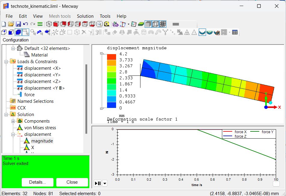
I have attached a sample model and a plot. The beam rotates on a pivot for half the load cycle (no strain), then a force kicks in to bend the beam over the support. In the resulting plot you can see that the rotation deflections dominate the result, making it difficult to assess the flex in the beam itself.
I am guessing there is a formula-based approach that will let us remove the rigid body component of the motion, but I think I'm missing a trick or two.
Any takers?
This can make it difficult to understand things like the flexure due to strain, or twist, etc. because the kinematic motion dominates the deflections.
I have attached a sample model and a plot. The beam rotates on a pivot for half the load cycle (no strain), then a force kicks in to bend the beam over the support. In the resulting plot you can see that the rotation deflections dominate the result, making it difficult to assess the flex in the beam itself.
I am guessing there is a formula-based approach that will let us remove the rigid body component of the motion, but I think I'm missing a trick or two.
Any takers?
Howdy, Stranger!
It looks like you're new here. If you want to get involved, click one of these buttons!
Comments
One can compare Principal Stresses , Strains and VM of the undeformed models to confirm the equivalence.
I have made some progress. Deviation with respect to the direct measure is below 0.3%.
Expected 0.1481 mm Direct Measure. Mean of the three nodes.
Final Displacement 0.1484 mm Castigliano
Deviation 0.25%
It requires some formula + minor postprocess but I think it’s worth as the idea seems full of potential, is elegant and generalizable for linear elastic materials under reasonable small displacements. I have use Castigliano′s second theorem. The good news is that Mecway computes the Strain energy for you.
1-Plot the overall Strain Energy of the whole system as a function of the external load P.
2-The displacement of the point of application in the direction of P is the slope of that curve (derivative).
I still need to explore it more in deep but apparently no BC conditions , geometry or rigid body (dU=0) to worry about.
-I set the modulus of the component of interest very high and re-run.
-I dump displacements for the "real" and "stiff" cases.
-I take the difference between these cases and create a big *BOUNDARY input file
-I use those displacements to run a dummy Mecway run
-The deflections show the flex displacements without the rigid body.
Pain in the neck!