Stuck?  support@mecway.com
support@mecway.com
Mecway
FEA
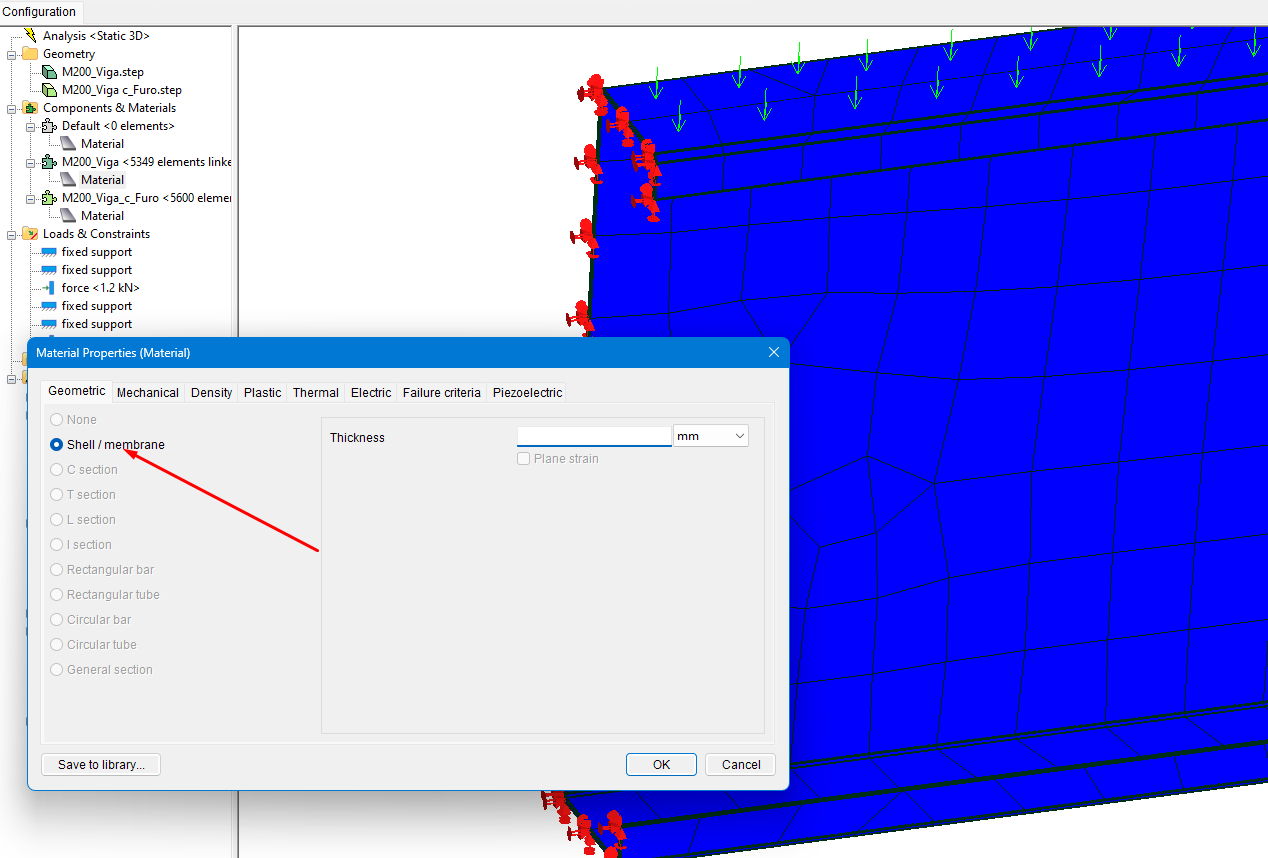
Inserting 3d file with STEP extension is asking for geometry thickness

Hello, I'm a new Mecway user. I'm inserting some 3D files and it's asking for profile thickness, could you help me? I've seen examples where thickness oppression is not requested.
It ultimately gives an error result like :Error: Invalid stiffness for element 1.
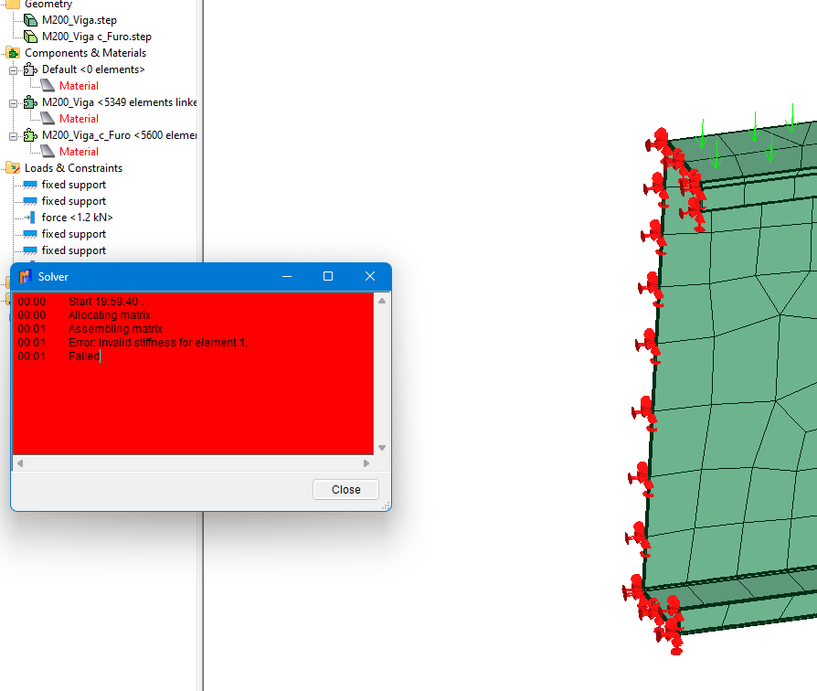
It ultimately gives an error result like :Error: Invalid stiffness for element 1.
Howdy, Stranger!
It looks like you're new here. If you want to get involved, click one of these buttons!
Comments
Ways to correct that:
Turn off Fit midside nodes to geometry. Easy but you lose the detail of the radius so it depends if you're interested in the stress there or the overall deflection.
Increase Min. number of elements per curve. 2 and 3 didn't work here.
Put a surface refinement on the inside radii. This removes most of them but produces a huge mesh over a million nodes at 0.8 mm Maximum element size.
Use the Gmsh mesher which is generally more robust but I didn't have much luck here.
For thin-walled prismatic shapes like this, you can get a higher quality and much lower node count mesh (hex-dominant instead of tet) by using Mesh tools -> Extrude from a surface mesh of one end. Delete the remaining surface mesh afterwards. Or possibly just model the cross-section shape alone in CAD then extrude it in Mecway.
Or use shell elements which is the usual way for thin-walled materials. Ideally, you'd model the midplane in CAD and do a surface mesh on that, but you could also use one of the surfaces of what you have and set Shell offset in Element properties to bring the midplane in the correct distance.