Stuck?  support@mecway.com
support@mecway.com
Mecway
FEA
Axial displacement of a supported beam end

Hello all,
I would like to know how much a supported beam end is moving axially when a force is applied in the middle of the span:
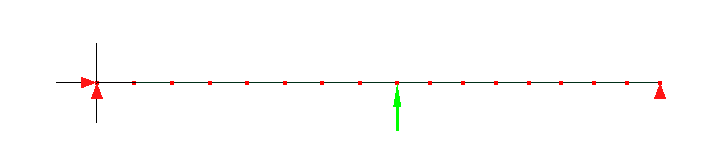
With the constraints in the above picture (end 1: displ_x=0; displ_y=0; end 2: displ_y=0), it shows that the displacement_x of end 2 is zero
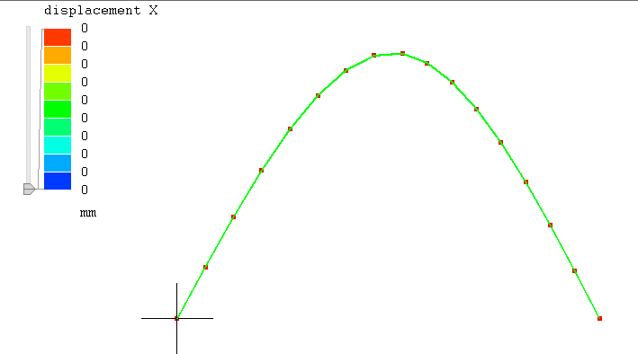
And I expected that the end 2 could move freely horizontally (along x)...
Thanks.
I would like to know how much a supported beam end is moving axially when a force is applied in the middle of the span:
With the constraints in the above picture (end 1: displ_x=0; displ_y=0; end 2: displ_y=0), it shows that the displacement_x of end 2 is zero
And I expected that the end 2 could move freely horizontally (along x)...
Thanks.
Howdy, Stranger!
It looks like you're new here. If you want to get involved, click one of these buttons!
Comments
But if it's really just a simple beam, probably easier and more accurate to use solids.
1. analisys -> check ccx solver
2. add ccx -> modify keywork -> *BEAM SECTION and check "omit keyword"
3. add ccx -> custom model definition and write: when I run the solver, it outputs What did I do wrong? I followed the cxx_2.16 manual, paragraph 6.3.3, but I am not sure what it U1 element. I am using line3, which corresponds to B32R in ccx. Any ideas?
Thanks.
Try to follow this liml file as reference.
Beams are not easy to apply Boundary conditions and these custom beams are known to have some limitations.Be sure to validate the beam before using it.
By other hand , once expanded, they end up as solids, so I don't really see the point to use them.
I have followed your example, and I have understood how to "assemble" a structural profile... but it is not valid to my case. I have a complex profile, whose properties are known (area, Inertia_y, Inertia_z). I would like to directly pass them to ccx to solve it.
So, after a little searching I have made the first attached file, with lineal elements, and I have got:
*ERROR in e_c3d_u1: no second order calculation for this type of elementThen I thought "this needs quadratic elements"
*ERROR in e_c3d_u1: no second order calculation for this type of elementAt this point I am totally puzzled
It is for this that it would be tough make it by composing rectangles...
I have tried and seems a plausible approach. ¿Does someone have experience with that?.¿Any warnings about it?
*SHELL SECTION,ELSET=Eall,MATERIAL=EL,OFFSET=0.0, NODAL THICKNESS
0.01
*NODAL THICKNESS
1, 0.0210
2, 0.0206
...
...
...