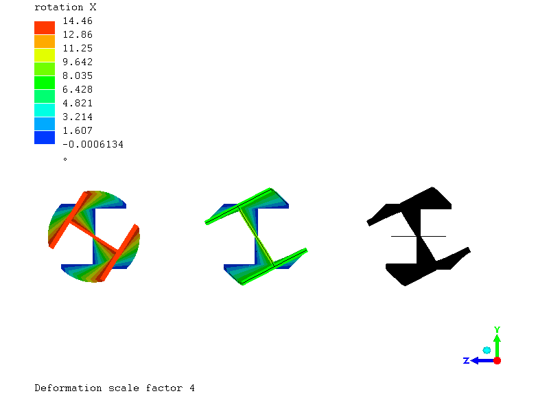
I beam torsion modeling
Hi,
I'm comparing 3 models of a I beam under torsion, one with just 1D beam elements, the second with 2D shell elements and the last one with solid elements.
The model with beam elements gives a maximum rotation angle of 14º, but the other models give maximum rotation angle of 9º.
Manual calculations give me almost 14º, but I'm not sure if I did it wright (I'm just a chemist, not mechanic engineer).
I couldn't find errors in loads and restrictions so I can't explain the difference.

I'm attaching the models file.
PS: There is no difference in the behavior of the 3 models when bending.
I'm comparing 3 models of a I beam under torsion, one with just 1D beam elements, the second with 2D shell elements and the last one with solid elements.
The model with beam elements gives a maximum rotation angle of 14º, but the other models give maximum rotation angle of 9º.
Manual calculations give me almost 14º, but I'm not sure if I did it wright (I'm just a chemist, not mechanic engineer).
I couldn't find errors in loads and restrictions so I can't explain the difference.

I'm attaching the models file.
PS: There is no difference in the behavior of the 3 models when bending.
Howdy, Stranger!
It looks like you're new here. If you want to get involved, click one of these buttons!

Comments
The torsion constants for beams assume they're free to warp regardless of the constraints, which is perhaps misleading.
I´ve also seen that there are several formulas for the torsion constant for this profile, so manual calculations may be between 9 and 14 degrees depending of the formula used.
I put something like a fixed diaphragm constraint (Y and Z constraints on the whole surface, and X constraint on one node for rigid body motion) on the shells and solids and now all 3 agree:
14.9 degree solids
14.9 degree shells
14.5 degree beams
Mecway shows the torsion constant that it uses for beams in the material properties box. It's using a formula from Roark's Formulas For Stress And Strain.
Roark's formula is an aproximate value.
It for this I section (r=0) is It=47.963 cm4
Introducing that value on a general beam section produces the exact result of 14.56º which agree with the analytical solution