Stuck?  support@mecway.com
support@mecway.com
Mecway
FEA
Dynamic HARMONIC analisys frequency domain

Hi,
I have given a first try to the Dynamic HARMONIC analysis in the frequency domain with some damping and as far as I have tested the results are correct to me.
The loads I have introduced have resonate at the right frequencies and trigger the corresponding deformation modes.
I still need to dig into it as I'm not used to this kind of analysis with FEA.
Traction, Gravity, pressure loads and moments works.
Imposed displacement doesn't seem to work ¿?¿?. Centrifugal neither.
It needs some custom cards but it's very simple. You won't believe it but I have start from a simple file and instructions given in a post of the forum (I would say posted by Victor) but now I'm unable to find it again for reference.
The file is called frequency response.liml.
I encourage you to try it. Much, much, much faster than time response.
Howdy, Stranger!
It looks like you're new here. If you want to get involved, click one of these buttons!
Comments
Is frequency response.liml this? https://mecway.com/forum/discussion/comment/5029/#Comment_5029
Yeessss.
I think it would be very appreciated.
Meantime users can try with custom cards:
Previous *STEP *FREQUENCY,STORAGE=YES is needed
*STEP
*STEADY STATE DYNAMICS, HARMONIC=YES
Sometimes it needs a GUI adjustment of the time period to see the results in the progress bar.
** Lower bound of the frequency range (cycles/time)
** Upper bound of the frequency range (cycles/time)
** Number of data points n (default: 20) (Shape accuracy arround the frequency)
** Bias (default: 3.). parameter to provide closer spacing of the results points either toward the middle or **toward the ends of each frequency interval.
1000,1600,80,2
**Damping definition.
** Recommendation: Define it. If default MODAL=DIRECT damping is considered, it might eat low frequencies.
** Do not overdamp the system if you want to see something.
**OPTION1
**Be sure to understand coefficients α and β before. You don't want to cut/loose some frequencies.
*MODAL DAMPING,RAYLEIGH
**• not used (kept for compatibility reasons with ABAQUS)
**• not used (kept for compatibility reasons with ABAQUS)
**• Coefficient of the mass matrix α.
**• Coefficient of the stiffness matrix β.
,,.6,0
**OPTION2
*MODAL DAMPING
**Default
**• lowest mode of the range
**• highest mode of the range (default is lowest mode of the range). Check last mode requested in the frequency step.
**• viscous damping factor ζ for modes between (and including) the lowest and highest mode of the range
**• viscous damping factor ζ typical values 1%-2%
1,4,.03
5,10,.03
11,20,.005
What you got there it's what's called a frequency response function (if you only imposed one load in one DOF, otherwise it's a summation of FRF's). I can't quite see the image clearly, but appears to me that you are plotting the imaginary values of the FRF. That is the first thing to note: I'd suggest requesting the magnitude and phase values, as it gives you a direct view of the shape of the motion and a more physical meaning.
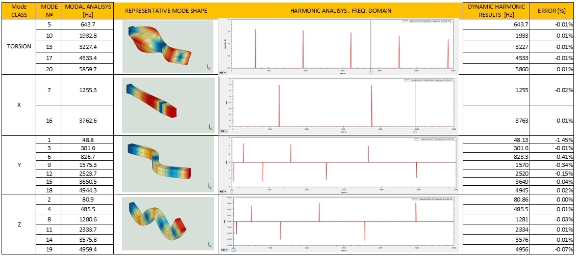
The other interesting thing to note it's about comparing results between natural frequencies derived from modal analysis and resonance frequencies in the FRF: to do this harmonic analysis, it's used the principle of mode superposition, so it directly uses the values of the natural frequencies and shape modes obtained in the modal analysis to construct the response. Then, in theory, you should get exactly the same data. The "error", even as small as you got, is due to damping, e.g you're getting the damped natural frequency, and a leakage problem due to the frequency resolution used to generate the curves. One caveat: you may not always see all the modes - e.g. the mode may not be sensitive to the load applied or you may be analysing a node of the mode - in a particular FRF, so beware of that.
Traditionaly the mode superposition uses FRF's and they are defined as a relationship of displacement to external load - here meaning force or torque, depending on the DOF -, so it isn't directly possible to do displament as external load. Centrifugal load presumes a rotational frame of reference. That'd lead to complex modal analysis, that's why it doesn't work, I'd assume.
About the damping models: I'd recommend always using modal damping only and directly assign damping factors to the modes. Since the implementation of the proportional model (Rayleigh) in CCX requires the input of the proportional coefficients, you may end up severly overdamping the lower modes more often than not, if, as Disla says, you're not familiar with the model.
The key in using harmonic analysis is guaranteeing that there's enough modes to correctly expand the response in the desired frequency. One way of doing that is analysing the so called modal mass against the inertia of the system. CCX provides this information in it's files.
To wrap it up, I cannot recommend enough the implementation of harmonic analysis (steady state dynamics) into the MW GUI. Usually, in structural dynamics, the excitation source is harmonic and permanent response may be more important than the transient one. So having this tool cut's immensely the processing time to get the desired output.
Thanks for comment. New subject so I appreciate it.
Right. Just in some cases. The tool is not implemented yet and Mecway can't extract it properly yet. I had to choose the most noticeable part to show a nice peak.
Right. I have start with a simple problem to be sure I was able to trigger all the modes and far from stationary nodes.
Right. Choosing as much modes as needed to reach a 90% of the total mobilized mass seems to be a good criteria.
Hope Victor can work on it too.
Thanks again.
Regards
I'd say that you're quite familiarized with harmonic analysis already!
Just to complement the topic of data form, to get magnitude and phase one should add PU under node file request, in CCX card, like so:
*NODE FILE
U, PU
I'd also call for normal displacement because otherwise MW doesn't show some deformed shape. Altough be carefull beacuse it only uses the real part of the displacement in the deformed shape.
Calling for U and PU, you'd get something like this:
For postprocessing, like I sugested above, I'd go with the the mag/phase format, together they form what's called Bode diagram and is of widespread use. The images bellow show the difference.
Best Regards!
just comment I can see both displacements, real and imaginary parts.?¿? I'm using v2.19.
Guess I better upgrade to 2.19, then. (I've been using 2.18).
Thanks for the tip!