Stuck?  support@mecway.com
support@mecway.com
Mecway
FEA
Strain rate dependency?

Hi ,
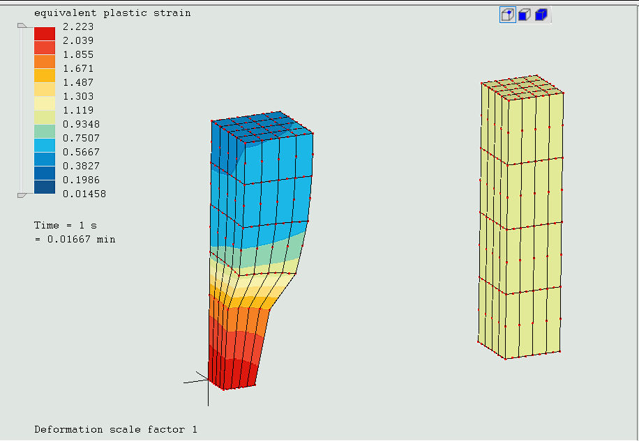
I’m not sure how to read these results. Seems automatic time stepping has some more curiosities.
I have set up two cubes with the same dimensions and I have applied to both the same stretch in a uniaxial stress state configuration. They both have the same material properties.
I'm considering incremental Isotropic Hardening (NLGEOM=yes).
The only difference between the two cubes is how I apply the BC (Strain rate).
The one on the left has an amplitude card in which the extension is applied with a sinusoidal shape, so the strains grow faster at the beginning of the time step and slower up to the end.The second is applied linearly.
Automatic time stepping is active so I can get easier the convergence.
Sinusoidal results are completely different. It shows necking and PEEQ is clearly high than the linear option.
¿How is this possible if ccx doesn't have strain rate dependency?
Regards
Howdy, Stranger!
It looks like you're new here. If you want to get involved, click one of these buttons!
Comments
Now, both parts show necking but in opposite ends and the linearly stretched part only shows it towards the end of the stretch.
Looking through the Calculix manual for this element, I find this text:
"This is an excellent element for linear elastic calculations. Due to the location
of the integration points, stress concentrations at the surface of a structure are
well captured. However, for nonlinear calculations the elements exhibits the
same disadvantages as the C3D8 element, albeit to a much lesser extent:
• due to the full integration, the element will behave badly for isochoric
material behavior, i.e. for high values of Poisson’s coefficient or plastic
behavior, i.e. for high values of Poisson’s coefficient or plastic behavior."
What I read between the lines is that the numerical error is not insignificant when the element becomes highly distorted due to such things as large amounts of plastic strain. Perhaps this is what would be considered a large amount of plastic strain and thus it is sensitive to errors.
I'm running your analysis with two levels of mesh refinement and the same small timestep as above but it will take about 3 hours to finish, so we'll have to wait a bit to see if this affects the issue.
Seems like for a uniformly stressed model, the plasticity may initiate anywhere.
The first point to start will concentrate the plastic strains. Something like saying a tensile test of a rectangular plate can brake anywhere, not necessarily at the center.
Time step = 0.01 and maximum time step = 0.1 with C3D20R generates a symmetric plastic strain pattern.
Apart from that , @Victor, seems like the Time step could have two readings ¿isn’t it?
Initial time step for Automatic and a Maximum time step for STATIC DIRECT
That's an interesting observation about necking initiating anywhere. I wonder if this sensitivity analysis that CCX seems to be getting will be able to identify things like this automatically?
Also worth noting is that your material model is only defined until strain levels of 0,94, after which it is considered ideally plastic. As all of the wierd behavior comes after strain levels above this, I'd definitely say that this is considered large values of plastic deformation.
As for your comment on whether necking may initiate anywhere, then I don't think that that is true but I'm a little bit in deep water here as I haven't got any calculations or simulations to back up my interpretation. My observation is that the element sides that have boundary conditions are kept flat while the other element sides are free to deform as interpolated by the 2nd order functions between the nodes. Thus, the elements at the ends will be forced to have a strain field that the other elements aren't similarly artificially forced to and thus the stresses may internally be a bit more concentrated in these end elements. I believe that this matters because I read different strain and stress levels in the corner nodes and in the midnodes even before the necking, leading to the conclusion that there's an inaccuracy due to the interpolation within each element and that the boundary condition may therefore affect how different this error is in the edge elements versus the elements further from the BC.
To graphically show why I think that the BC is influencial, we can look at the equivalent plastic strain distribution at the end of the linearly strained part and see that it is clearly not constant across the face. This is to be expected as the boundary conditions are like symmetry planes but still, thinking about that they constrain the strain field within the element, I am convinced that this forces the necking to appear at one of the ends.
To bring it back to the original question of strain rate dependency, then I do not think that this is the case but that if the behavior seen is driven by numerical inaccuracies, the difference between the two load cases may be explained by the fact that the load increases differently per timestep for each of the two parts and thus, the problem is timestep sensitive.
Due to the deformation at the end being concentrated in few distorted elements near a BC at strain levels far beyond the material model, I do believe that this simulation is not a trustworthy representation of reality. Thus, I'm not convinced that this is actually a problem for using this element for engineering purposes.
My main concern now is that, if an analysis is timestep (or I would better said, time shape) dependent, I haven’t been paying enough attention to that point.
I know some problems like thermal , are very sensitive to mesh size / time step ratio but for mechanical problems I thought automatic time step was taking care of the problem accuracy once provided the right mesh size as there are some parameters which must be below certain values before proceeding with the next increment.
largest residual force= …….
largest increment of disp= …….
largest correction to disp= ………..
It seems that for plasticity that’s not enough.
I think I must focus now to find a good time shape function , sensitive enough to initiate the plasticity at the right area and smooth enough to promote convergence.
It’s too early now but I think I have the perfect candidate in mind. I must check if it can trigger the right solution where the other too are failing. I will report and thanks again Sebastian.
My bet is that it's equally correct wherever it happens and nothing to be concerned about.
¿Is there a strain rate different from linear which can provide a better result for the same time period/step/mesh configuration?. That’s the point.
This bar must show necking. Under the same mesh refinement , linear strain rate has not been able to initiate it and result is still very far from the right one.
I have compute Prof M.Kraska example Tensile test on a wire.
For the same BC/mesh/material/Time period and Time step configuration (Automatic) ,
Linear strain rate:
Total CalculiX Time: 99.400074
Max PEEQ = 2.003
My new candidate:
Total CalculiX Time: 274.449488
Total maximum increment size has had to be increased if not failed.
Max PEEQ = 1.744
One provides better accuracy given the same set up.
¿Which is the best one?......
I get 2.214 vs 2.223 max. PEEQ which seems like a smaller difference than @Sebastianmaklary got?
I managed it without refining the mesh by slightly moving one node.
Removing elements in the center did force the necking to occur here but that's a bit extreme.
I just noticed another thing: The equivalent plastic strain is two orders of magnitude lower than the total strain, which indicates that the majority of the strain is elastic strain, right? Either, I've completely misunderstood what Equivalent plastic strain is, or something is really off. A 1st principal strain of 126 with a plastic strain of only 2,8 seems wierd.
https://github.com/calculix/CalculiX-Examples/tree/master/NonLinear/TensileTest
At the beging I though, that is a trick!, but then thinking more deep, in the real test, the necking would start also in some imperfection, dimentional or in the material, so is ok to introduce it in the FEA model as well. If the test sample is measured with a caliper, maybe an imperfection of 0.001-0.005 is not visible, and enough to start the necking there.
PEEQ seems right. Incremental plasticity provides the Lagrange Strain. To be able to compare with PEEQ you need to compute:
Ln(sqrt(2*126+1))=2.77
@disla, so the strain results in Mecway are all engineering strains, apart from the equivalent plastic? I was not aware of that. Thank you for bringing it to my attention. Good to know that this is not an error in the program.
No. I wish it were that simple.
Incremental plasticity and Hyperelastic models are Lagrangian,
Deformation plasticity is Eulerian but will be updated to Logarithmic in next ccx version.
However, refining the same mesh put it at the notch! Yay. Now I'm (probably prematurely again) satisfied that nothing's wrong.
Jakub Michalski on the ccx forum provided a good reference for the final PEEQ on this problem which help me to progress.
For some reason that I still don’t fully understand, the automatic time increment setting , when it founds a linear function as BC , It speed up the convergence process increasing the time increment if things are going fine. That reduces the final accuracy of the PEEQ value (PEEQ is an accumulated value along the whole time period and looses accuracy if the time step is too large.)
When one considers a nonlinear function to input the BC, ccx seems to be forced to keep the time increments small no matter how good the convergence is, providing a final PEEQ more accurate and close to the correct result (larger computation times too).
My final conclusion : When computing plasticity , set up a maximum time step or even better, perform a convergence study reducing the maximum time step.
Example with Automatic set up for Mr. Kraska tensile test of wire:
NO Maximum time Step Final PEEQ =2.003
Maximum time Step=0.2 Final PEEQ =1.75
Maximum time Step=0.01 Final PEEQ =1.68
Linear function like A=0.3*t is discretized with just two points.
0,0
1,0.0003
It makes the automatic time step to increase more and more as the convergence is going fine but it’s a false improvement for plasticity. That makes PEEQ to end up at a value that is not accurate.
I didn’t notice this problem because VM in plastic analysis remains bounded by the flatness of the Stress-Strain Curve so you can have a wrong True Strain 400% times bigger than the good one and VM still be in perfect agreement on top of the Stress Strain curve (Specially in perfect plasticity).
Maybe a minimum number of points could be added but, as I understand in your comments adding points manually is not enough. Mmmmmh.
I have been experimenting with Hermite polynomials to replace the linear function when introducing Quasi-static BC.
There are some versions, but there is one…mmmh..
Very smooth on entry and at the end. Non-linear all the way so it allows some boost but at the same time forces ccx to keep the step size under control in automatic.
It has delivered the same result as Abaqus Explicit in the M. Kraska tensile test with frictionless support on both sides (Necking in the middle).
Mecway discretize it with 108 points (which is by the way a beautiful semiperfect number).