Stuck?  support@mecway.com
support@mecway.com
Mecway
FEA
Cyclic symmetry stepped modes extraction from nodal diameters

Hi,
When using Cyclic symmetry, one can predict the number of modes internally computed and modes displayed as:
-Modes displayed = Nº of requested modes * Rounded to lower integer(Nº of sectors /2 + 1)
-For frequency calculations with cyclic symmetry the eigenmodes are generated in pairs (different by a phase shift of 90 degrees). Than means the number of modes internally computed = Modes displayed x 2
EXAMPLE:
Let’s say I want 10 modes and my Cyclic symmetry has 12 sectors:
10* Rounded to lower integer( 12/2+1)= 10 *7=70 modes
Due to the fact that each mode has a clockwise and anti-clock wise solution, the number of internally computed modes is the double.
Number of modes internally computed = 70 x 2 = 140
Meaning that for 12 sector Cyclic symmetric model, requesting 10 modes requires an internal computation of 140 modes. Even known that, it is faster than the full model.
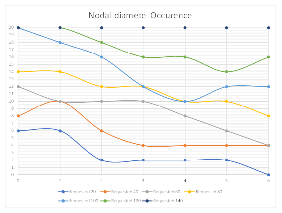
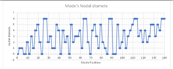
If one sorts the computed modes by increasing frequency, one can realize that:
1- The nodal diameter from where the next lowest mode will come from seems unpredictable. See graphs.
2- But…..if one focuses only on the first requested number of modes , one can realize that the list is filled first by the lowest nodal diameters with less and less occurrence from the 2nd, then 3rd, 4rth and so on.
My question.
¿Could we in a safe way adjust the number of requested modes for Cyclic Symmetric models in a more stepped way?
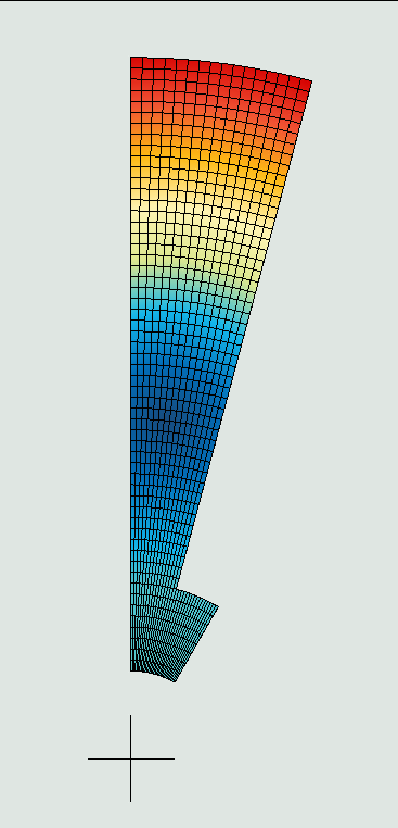
I have done some preliminary testing on a model with the structure presented at the beginning of the post and I can get the same 10 first modes with a computation time less than half requesting a steeped number of modes. It doesn’t even look like I’m losing any accuracy.
Changed the default setting :
*STEP
*FREQUENCY
20
*SELECT CYCLIC SYMMETRY MODES,NMIN=0,NMAX=1
*NODE FILE,GLOBAL=YES
U
*END STEP
*STEP
*FREQUENCY
20
*SELECT CYCLIC SYMMETRY MODES,NMIN=2,NMAX=6
*NODE FILE,GLOBAL=YES
U
*END STEP
Substituted by this:
*STEP
*FREQUENCY
8
*SELECT CYCLIC SYMMETRY MODES,NMIN=0,NMAX=3
*NODE FILE,GLOBAL=YES
U
*END STEP
*STEP
*FREQUENCY
6
*SELECT CYCLIC SYMMETRY MODES,NMIN=4,NMAX=5
*NODE FILE,GLOBAL=YES
U
*END STEP
*STEP
*FREQUENCY
4
*SELECT CYCLIC SYMMETRY MODES,NMIN=6,NMAX=6
*NODE FILE,GLOBAL=YES
U
*END STEP
When using Cyclic symmetry, one can predict the number of modes internally computed and modes displayed as:
-Modes displayed = Nº of requested modes * Rounded to lower integer(Nº of sectors /2 + 1)
-For frequency calculations with cyclic symmetry the eigenmodes are generated in pairs (different by a phase shift of 90 degrees). Than means the number of modes internally computed = Modes displayed x 2
EXAMPLE:
Let’s say I want 10 modes and my Cyclic symmetry has 12 sectors:
10* Rounded to lower integer( 12/2+1)= 10 *7=70 modes
Due to the fact that each mode has a clockwise and anti-clock wise solution, the number of internally computed modes is the double.
Number of modes internally computed = 70 x 2 = 140
Meaning that for 12 sector Cyclic symmetric model, requesting 10 modes requires an internal computation of 140 modes. Even known that, it is faster than the full model.
If one sorts the computed modes by increasing frequency, one can realize that:
1- The nodal diameter from where the next lowest mode will come from seems unpredictable. See graphs.
2- But…..if one focuses only on the first requested number of modes , one can realize that the list is filled first by the lowest nodal diameters with less and less occurrence from the 2nd, then 3rd, 4rth and so on.
My question.
¿Could we in a safe way adjust the number of requested modes for Cyclic Symmetric models in a more stepped way?
I have done some preliminary testing on a model with the structure presented at the beginning of the post and I can get the same 10 first modes with a computation time less than half requesting a steeped number of modes. It doesn’t even look like I’m losing any accuracy.
Changed the default setting :
*STEP
*FREQUENCY
20
*SELECT CYCLIC SYMMETRY MODES,NMIN=0,NMAX=1
*NODE FILE,GLOBAL=YES
U
*END STEP
*STEP
*FREQUENCY
20
*SELECT CYCLIC SYMMETRY MODES,NMIN=2,NMAX=6
*NODE FILE,GLOBAL=YES
U
*END STEP
Substituted by this:
*STEP
*FREQUENCY
8
*SELECT CYCLIC SYMMETRY MODES,NMIN=0,NMAX=3
*NODE FILE,GLOBAL=YES
U
*END STEP
*STEP
*FREQUENCY
6
*SELECT CYCLIC SYMMETRY MODES,NMIN=4,NMAX=5
*NODE FILE,GLOBAL=YES
U
*END STEP
*STEP
*FREQUENCY
4
*SELECT CYCLIC SYMMETRY MODES,NMIN=6,NMAX=6
*NODE FILE,GLOBAL=YES
U
*END STEP
Howdy, Stranger!
It looks like you're new here. If you want to get involved, click one of these buttons!
Comments
This is now possible because I know a priori the occurrence of each Nodal diameter. In any case, a gentle steep by pairs of Nodal diameters seems safety.
Any suggestion on how this could be safetly steeped is welcome.
that's interesting, thanks for sharing. my experience was a lot easier. we only did one blade as a shell model. we were mainly looking for the first 3 modes. 1st flat wise, 1st torsional, and 1st edgewise. We also looked at the 2nd of each. The reason for the analysis was to place strain gages for flight testing and know what frequencies corresponded to what modes. We made campbell diagrams also. Luckily, we didn't have to solve for vast amounts of modes.
During some recent mecway/ccx testing, I ran into the issue you mentioned of laborious output processing.
Cyclic symmetry did a great job of simplifying it. It only outputs legitimate full rotor modes.
Full rotors, with flexible hubs, was a mix of what you would want to see and random modes. There would be whole rotor modes (same as cyc sym), but also random modes would pop up. They seem to be some sort of garbage.
If the hub was rigid, then each blade had it's own output result, even though it was at the same frequency and of the same shape. So if you wanted six blade modes and had eight blades, you would have to run 48 modes. Thus, if the hub is rigid, it's a lot better just to run one blade. Both full rotor tests ultimately could confirm the cyclic symmetric equivalents. However, it was a lot harder to get to what you want to know, using full rotor models.
Unfortunately, cyc sym becomes so slow, that it's not usable most of the time. Cyc sym also reduces the usable node count by a lot. One test case I did, ccx took 29 mins to complete, then mecway too another 49 mins to process what ccx did and go back to the gui. the model only had 252,207 nodes. that was maxing out my 16gb of memory too. With nl static and regular modal analysis with linear prestress, I can solve around 1 million nodes. So it's a huge drop in model size and a huge increase in solve time. Thus, I never use it, other than testing. It is neat to see all the nodal diameters though.
I'm not sure if what I have exposed has been understood.
¿How many modes have you request in your 7 Blade Rotor?
yeah, i don't know about your original post. i was commenting on @JohnM reply. however, i requested 6 modes and there are 7 blades. so that works out to 24 final modes (due to nodal diameters).
in a different thread you mentioned just outputting a single sector. i had tried that in the past and it was faster. i didn't realize how much faster though. also, the model size / memory amount penalty involved.
so while i can't really output the whole rotor with cyc sym. i can still at least output a sector. it's a lot nicer using cyc sym. even if just one sector is output. there are no random unexplained modes. just the whole rotor modes. so much easier to go through. everything is significant that is shown.
¿Do you mind if I post some images to explain what I'm talking about?.
- Solve for 1 mode of each ND.
- Pick the ND with lowest frequency mode and solve for an additional mode of that.
- Repeat until you can confirm you have the lowest N modes overall.
There's time wasted solving the same ND multiple times but you also save time by never finding the higher modes of the unneeded NDs so perhaps it ends up faster overall.You found that the duplicate modes represent the opposite direction of the rotating mode? That finally explains why they're there in addition to the imaginary parts.
This morning I have wake up remembering a conversation long time ago with a friend of mine. If a non-speaking English person try to predict the next letter in a text will probably conclude that it is unpredictable.
But if you look at the English Letter Frequency based on a large sample of words….baaaammmm.!!!
I think this might be related in some way. Any mathematician in the room.!!!. Or any Student?. This is well worth a thesis.
I was also afraid that the shape may depend on the number of modes but that’s not the case. Given the same number of Nodal diameters , the modes always show up in the same order no matter how many modes I request.
Thats important because if someone has to repeat a modal analysis for small adjustment, you could request no more no less, just the required number . That could be a lot of time saved on that second run.
sadly, i'm totally lost on what your original goal is. one thing i can say as far as the nodal diameters repeating. it seems to depend on the model. if there is a flexible hub then the mode frequencies are not the same as the nodal diameter goes up.
i have a bunch of models for two different configs. however, i'm using a beta version of Mecway. so not sure if you can open them. i would also have to clear the results. so you would have to resolve and that takes a long time (i have been running them for the last few days, due to hooshsims thread). not sure there is any benefit for you though, as they are nothing special.
do you know what 'beautiful rotor liml file' you are talking about. i don't remember. i wrote a propeller design code called PROP_DESIGN. it can create propellers, fans, turbofans, rotors, stators etc. you can make a lot of cool looking blades. i import points, from PROP_DESIGN, into Rhino. Create a step file. Mesh that in Netgen. Import the vol file to Mecway. That's the best work flow I have found. PROP_DESIGN is public domain software. You can find it via google search. However, it would take a lot of work for people to understand how to use it. Creating the cad models is the worst part. I used to have youtube videos about the program, but have removed them. Too time consuming to keep them up to date.
anthony
I have sent to you a private message.
I'm not questioning how many modes should be reviewed, what I'm exposing is that if the designer request 10 modes (he will know why) there is no need to compute 140 as it happens now. No matter if they could be useful or relevant. Maybe, requesting 10 modes is enough and the designer has already include some additional modes to be conservative.
I'm finishing some tests that I think may shed some light on the subject. In the meantime, some other questions have arisen to me about cyclic symmetry.
I would say there is a best way to extract the modes when combining Frequency + Cyclic Symmetry. Let me know what do you think?
-One can request a steeped number of modes (we can talk about that later).
-Sort the frequencies and take note from which ND it comes from each one.
-Sort the lowest number of modes requested by the user. (let’s say 10).
IMPORTANT PART
-Check if all the Nodal Diameters have at least one mode that is not included in that list of the lowest modes. The answer is in the “remaining” , “unused modes”. (This is also a very inclusive strategy
If each ND has at least one mode out of the list, it means it had the chance to enter but it didn't because is already full of lower modes than him. So, the extraction is right, and we are sure we have the lowest modes.
If some ND is not represented in the “>10 modes list” , it means there is a chance that we missed one and we should rerun adding some more nodes but…… just for the specific ND that did not pass the test.
I think ccx allows to request modes but just starting from a certain frequency not from the beginning. That would mean to complete the list without having to compute everything again.
Reducing the number of modes extraction has a huge impact not only in computation time, also in postprocess, overall file size, the ease and speed of user interface and the clarity of solution.
CCX's feature to specify the minimum frequency still solves for the lower ones but just doesn't output them, but it would certainly help speed up loading the solution as you said. It would be great if we could solve for a specific mode number but I don't think ARPACK has that capability.
I don't think that's possible. Anyway, the first extraction would have shown all the first positions occupied by the last ND. On a second run the user would have to increase just the highest ND number of modes probably decreasing all the others. I have been able to compute a fan that wouldn't have been possible in my computer in any other way (16Gb). The first torsional mode was at the 6th position of the first ND. That represents to compute 128 modes , most of them useless. I can reach it just with 20 modes if the extraction is selective. Even with this technique it takes 53 min.
Imagine what would have happen to the GUI to process 128 modes with 627.000 nodes each one. (I have output only three blades).
The idea is here in the post. Users can try if they find it usable.
By other hand, love the new version. Shape modes have much more sense now. I can't resist to post other model. It could be one of the strange creatures from Captain Nemo.
It's all described in the first post. Including ccx cards.
Read the procedure carefully or you can skip some important modes.
In addition to your CCX cards given on top of this thread for sector model, do I need to include the following cyclic cards too? This is what I’ve been using in my sector models
*TIE,NAME=c, cyclic symmetry
Surf1,surf2
*cyclic symmetry model, N=7,ngraph=7
0,0,0,0,0,0,1
You need to modify the STEP by first "don't generate the Step" and later write it yourself.
Centrif can be NLGEOM if you need it. Prop_design recomends to activate it.
the animation @disla showed is from a model I sent him. it's one of two old test models that i made a long time ago. i have been re-running them since you're post about full disk modes. i just finished remeshing and solving one of the models. so it's smaller now and solves faster.
here is a link to the latest versions of the models; https://1drv.ms/u/s!AubMNYNIQyqKgnZtQlABvKjdYm_R?e=sJ7vly
note; the link will only be active for a few weeks, as I need to conserve the online file storage. so download it while you can. these are models I previously sent @Victor as well.
ps; the v19 cyclic sym animation feature is on the labs tab. you have to run small models to be able to use cyc sym and animate it. on my laptop with 16gb of memory, the max nodes i can solve is about 250k before it goes out of core. to run efficiently it's about 100k. so the feature isn't really usable for realistic models. most nl static and prestressed modal runs, with fixed bc, can solve about 650k nodes. so there is quite a drop in modal size when cyc sym is needed.
anthony
ps; i should add a few things
i put (recommended) in the file names of the best way to run each model. you can run all of them if you want though. for rigid hubs, one fixed blade is fine. for flexible hubs you need cyc sym. outputing only one sector reduces the memory requirement and solve time. one model is for the A400m PROP_DESIGN example. The other is for the original Delta computer case fan example. The whirling disla showed isn't what you should get out of that example. i only looked at the first nodal diameter with that. the whirling shows it needs to be fixed at the back of the hub, when doing cyc sym. however, i wasn't looking for that in that example. however, the whirling from the computer case fan example would be real.
also, that a400m model is grossly simplified so that i could run it through all the tests. the actual mesh is in a different folder that i didn't send. it's so big you can only run one fixed blade. so the results for that should not be taken literally. it was just a test of mecway/ccx features.
the only thing that might help some is if the hub is rigid. then there were no unexplained modes. it just repeated each blade individually, instead of them being all in one mode, like it should be.
that issue is what i was talking about in a different thread, regarding @hooshsim full rotor asymmetric model. it's going to be hard to sort through the results of that type of thing. you end up having to solve for a lot of extra modes because it throws in a lot of unexplained modes. it seems to be the number of modes that you want * the blade count. however, for an asymmetric model, i have no idea what might happen. i've never run one of those.
the animation you posted showed me i should have constrained that model some more. however, it didn't affect what i was looking at. sorry to have caused confusion. another good find by you. the computer case fan model does the same thing. but the blades are shorter. so it may not look as cool. the whirling in that example is real though.
i've been running these same examples for 15years or so. so they have lost their cool factor for me. however, i'm glad you like them.
ps
i'm going to try just rotating the single sector mesh in mecway and joining it, to make the full rotor. maybe that will get rid of the unexplained modes.
oh darn. i forgot. netgen doesn't match faces. so when you rotate one sector, the elements/nodes don't line up. that's the same reason i can't use mecway's cyc sym constraint. oh well, worth a try.
Do you have any recommendations on how to get accurate frequencies using cyclic symmetry analysis? Thanks again.
oh i should add, use calculix for cyc sym. mecway requires the master and slave surfaces to have the same mesh. netgen doesn't have a way to force that to happen. so it's unlikely they will meet the mecway internal solver. maybe someone else knows how you can force that. in ansys it was possible to do. of course, on one of those models, i have a really crazy cut surface going on. so those surfaces probably could never have the same mesh anyway.