Stuck?  support@mecway.com
support@mecway.com
Mecway
FEA
Weird behaviour in Shells when using composites

Hi Forum,
I am experiencing really weird behaviour when working with shells. I have a tube made from shells. One side is fixed the other side has a rotation of 3°. I defined a laminate with 5mm in total. The tube is geometrically splitted in half. Therefore I mesh it with Gmesh and copy the elements to the other side and then connect the nodes on the mirror plane. When I first let the simulation run I get weird behaviour for moments per length.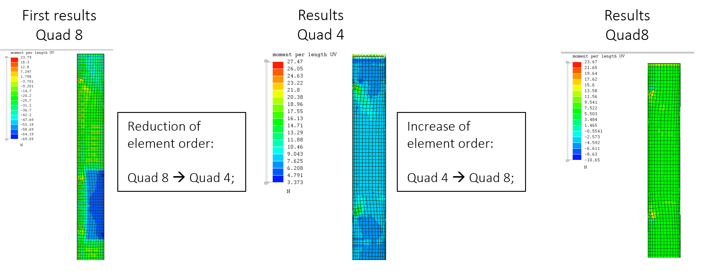
When I then change the element formulation to reduced elements (Quad4) and change it back to full integrated Quad8 I get a different and more homogeneous result.
How can this happen ?
greetings
Howdy, Stranger!
It looks like you're new here. If you want to get involved, click one of these buttons!
Comments
edit 1; oops. now i see it. not sure what that is. maybe victor will have an idea. the disp are about the same. but that particular plot is weird for the quad 8. i had been looking at the quad4 plot.
edit 2; oh i think i see the problem. when you switch to quad4 it changes the element shape. when you switch back to quad8 it's not the same shape as the original. those truss elements that were connected to the midside nodes are no longer connected to anything. if you want to do this comparison, i would delete all the truss elements at mideside nodes. that way you should be able to at least switch from quad8 to quad4. but when you switch back again to quad8 it looks like different geometry than the original.
You will get spiders dropping out when stepping down from 2nd to 1st element order. Easy enough to delete the SPDRS component and refresh the Spiders tool when ramping back to quadratic elements, especially if one has saved the edge surfaces beforehand.
I think it might be either the process of merging the tube or the gmesh commands...
Attached is a sample model with a basic mesh and no merging nodes which still behaves weird.
Maybe someone can run it on their system ?
Quad4 is also pretty bad for curved geometry because it doesn't have enough nodes to be curved in arbitrary directions. This works better with the CCX solver because CCX determines the curvature by averaging the angles of the adjacent elements instead of just using the element's own nodes.
I also notice the nodes don't have a very uniform radial distance from the axis.
Mesh refinement and fitting the nodes to a cylinder (Mesh tools -> Project onto surface) makes a more uniform solution.
Any ideas ? Could it be the internal solver ?
-I have also found some small jumps on areas where the mesh was irregular, or density changed. Not sure why. I' doing more test. For a uniform mesh and after refinement that difference almost disappear except close to the lib of the shell.
-Regarding the perimeter of the Spider beams, I think your BC is drilling the lib of the shell. You want to rotate the cylinder as a whole not the nodes individually. I think spiders should be used constraining the rotation of the interconnecting nodes. If not , I don’t think you can assure you are rotating 3º.
Your results look like its averaging node values with internal axis pointing in different directions. Is that possible?
¿Could you share the exact solution for this model or provide the reference to locate it please?.
I'm very interested in checking the solution.
Thanks in advance
I did some more research and the results just don't match up..
Once I introduce Trias the solver mixes things up for Failure Index, Stresses and so on. I also tried a normal isotropic material. Again this is a tube with a torsional moment at one side and a fixed support on the other side. Feel free to download the models below. I also checked the element orientations when I switch the Quad8 to Tria6 and they look good. Did somebody else experienced similar things ?
I won't do a comparison to calculix because I need the failure index for CFRP calculation, which is calculated by the internal solver.
3543 nodes (your model):
FoS quad8 = 1.8
FoS tri6 = 2.3
14050 nodes (after Refine x2):
FoS quad8 = 2.1
FoS tri6 = 2.2
I have found, with the help of @disla, that the UV moment depends on the element node number ordering. This is concerning because I don't think that should affect the results, but it isn't a problem in these cases or any case I've seen because the values are all error anyway and approach zero with mesh refinement.
I Compared Quad8, Tria3 and Tria6 with the internal solver and Tria6 with Calculix together.
When I only compare the two solvers (Calculix & Internal) with the same mesh, then one can see that there is more deviation at the internal solver.
While a mesh refinement "fixes" the issue because then the deviations of the middle knots become smaller it is not really practical to refine the mesh so much. Even for this sample model it increased calculation time a lot. So maybe Victorcould you take a look at the functions of the Tria6 middle knots ? Doesn't look right that the values jump around that much in both directions while at calculix they are just a little bit lower and all three middle knots at calculix are similar.
In this model, the internal solver's quad8 seems to be about 10% low on max. shear stress x2, improving to 5% with 4x refinement, while CCX remains within 0.2% of the same value with refinement to 1x, 2x, and 4x the number of elements. It could be that CCX is better suited to thick shells like these. I'm not sure.
Be aware that you shouldn't use tri3 or tri6 shells for the whole model with the internal solver because they have known hourglassing modes and need a lot of refinement to compensate for their poor accuracy.