Stuck?  support@mecway.com
support@mecway.com
Mecway
FEA
Topology optimization using Calculix
Hi there
While searching for an affordable topology optimization software, I found out that someone has made an open source python code for performing topology optimization using Calculix with FreeCAD as a user interface.
Could this be useful for implementing topology optimization into Mecway?")
The links that I found are these:
https://forum.freecadweb.org/viewtopic.php?t=15460
https://github.com/calculix/beso
While searching for an affordable topology optimization software, I found out that someone has made an open source python code for performing topology optimization using Calculix with FreeCAD as a user interface.
Could this be useful for implementing topology optimization into Mecway?
The links that I found are these:
https://forum.freecadweb.org/viewtopic.php?t=15460
https://github.com/calculix/beso
Howdy, Stranger!
It looks like you're new here. If you want to get involved, click one of these buttons!
Comments
I tried it out last christmas and it works.
What I want to do next is to retreive the beso configuration file and run it directily on calculix (without using FC). You need to install python.
Could you clarify what you mean by running it directly on Calculix?
I have only ever used Calculix with FreeCAD or Mecway as a user interface and are interested in if this could enable topology optimization using Mecway.
My clarification about the procedure I am thinking about:
1. Draw the 3d model on Freecad-FC(which is "sometimes" a pain).
2. Set the finite element model on MW.
3. Export the *.inp file. This is an export option on MW.
4. Run BESO-CCX -python script(domains, features, etc) in order to perform the topology optimization.
5. View results on Paraview or FC. Maybe on MW?????
Manuel
Just an update: It works. I set up an analysis in Mecway to be run with Calculix, run the analysis, click "details", then the .inp file button which opens a .txt file which I then save as .inp. Then in the beso python script, which I open with Spider through Anaconda Navigator, I set the path for Calculix and the inp file in the beso_config.py script and also here, the settings are entered.
I have successfully replicated the 2D example and I have run optimization on a 3D beam, where I set "do not alter"-zones by setting some elements as separate components in mecway.
While the beso script runs, it makes new .inp files for each iteration, which are then either all saved or is saved at specified intervals. These can then be opened in Mecway again by use of the "import" button in the file tab. When importing, it is however just a dumb mesh, which makes it a bit bothersome to set up the analysis of the final geometry if if is not very very simple. If it was ever implemented as a functionality of Mecway, perhaps loading the resulting mesh and analyzing it could be more elegant.
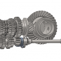
The picture above shows iteration 100 out of 284 iterations which took 1h 35min but the final iteration was basically a thin stick connecting the fixed end and the loaded end because the load I applied was very low.
I have yet to discover which settings to use to get a good result and also how to postprocess it into a usable CAD file but that's an ongoing learning experience.
As I investigate with it, I find some tips and tricks that I'll share here. First is that the faces/elements with boundary conditions or loads should be marked as non optimizing zones as the program will otherwise remove elements even though they are loaded. The total load onto the mesh doesn't change as the elements are not actually removed but are just switched to a much lower youngs modulus but this could lead to incorrectly applied loads and deformed meshes.
The second tip is that the non optimizing zones should be at least two elements thick when dealing with tetra elements as they will otherwise end up just connecting at a node and thus making a hinge when the connecting elements are switched to the softer state. The elements won't undergo rigid body movements as they are still somewhat supported by the very soft "removed" elements but it is clearly not as intended. To easily make this non optimizing zone 2 elements thick, start by using the edge detection selection tool in Mecway to select a face and add it to the component that has the non optimizing elements and then hide this component. Then use paint select to select the newly exposed elements and add them too.
Regarding importing the mesh, do they include *ELSETs, *SURFACEs, or anything that Mecway could merge with existing components/named selections when you import?
The code that exports the inp files are only 60 lines and seem fairly straight forward, though I'm used to Matlab, not Python, so I imagine that amending that code to export what is needed for Mecway should not be too much of a headache. If I understand you correctly, the beso script should export some named selections of the faces or nodes for each load or boundary condition which I can then use in Mecway to apply the forces used in the initial setup. Is this correctly understood?
Yesterday I ran a sample beam with a more suitable load magnitude and after 3 hours, the 148th iteration looks like on the screenshot below. I'm very impressed by how even the stresses are. The von mises stresses are between 38 and 55 MPa in the middle section and then there's some stress concentrations at the edges of the fixed end due to unrealistic boundary conditions.
This however exposes the need for more refined selection tools in Mecway as I want to use the paint tool to "paint" the initial seed but currently, only the surface elements can be chosen this way, which is "no bueno" with a solid model. An improvement to this tool could be an option to set the selection depth to either some number of elements deep, some distance deep or through all.
Also an "expand selection to touching elements" could be useful for making an element selection multiple elements deep after using the edge selection detection to select a surface.
Such selection tools would make it much easier to sort our mesh into a design space, no-design spaces and initial seed.
Making the seed by making the seed geometry in my CAD software and having bonded contact between the initial seed and the design space is also an option but I'd prefer not having contacts unless they are needed.
Another selection tool that could be usable would be a boolean selection tool that selects the elements that are within some imported geometry or that overlaps with another mesh. Then I could use a conventionally designed part to select elements from my design space to put in another component that is the seed.
At the moment, I'm testing with a geometry that resembles a wishbone in an automotive suspension and the optimum after 160 iterations during an hour is not surprisingly a very simple truss-like structure.
How much time takes to reach this configuration? I will give a try to BESO, looks interesting.
Do you know what could be wrong? I have edited beso_conf.py (only changed the path to ccx) and install some Phyton library needed (with pip install...).
By the way, I'm using ccx 2.20, and have tested before solving the Plane_mesh.inp separately and it works ok.
In spyder however, it seems that the next step after where you're stuck is making figures so I guess that that may be the issue. I don't know how plots work in IDLE though..
Here's what the start looks like here: