Stuck?  support@mecway.com
support@mecway.com
Mecway
FEA
Shell Model - Flexible Panel With Outer Frame

Hello,
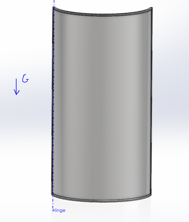
I am trying to model a thin curved panel with a relatively thick outer frame. The assembly has a hinge interface on one side, and I am interested in how much deflection there is at the other side caused by the weight of the components. I tried making a shell model of the assembly, which worked well for linear analysis, but I am having a hard time getting it to solve when I transition to a nonlinear model which is needed due to the large deflections. I am using the elastic option for the bonded contact in the nonlinear case, and I am getting "nonpositive Jacobian determinant" in some of the elements of the main shell.
I've also tried replacing the frame components with solid bodies, but I have been getting errors with "Too many cutbacks" when I do this.
Any feedback, or suggestions would be greatly appreciated.
Thanks,
Paul
Overall Assembly Image:
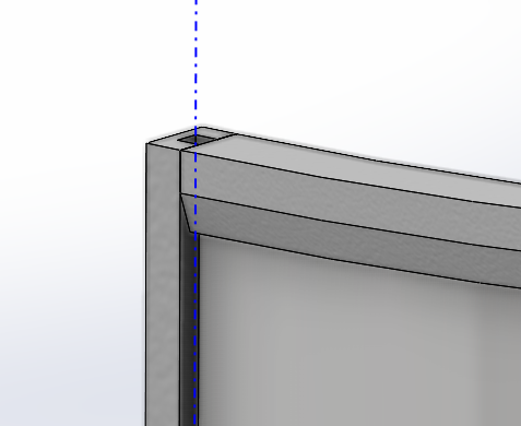
Frame Image:
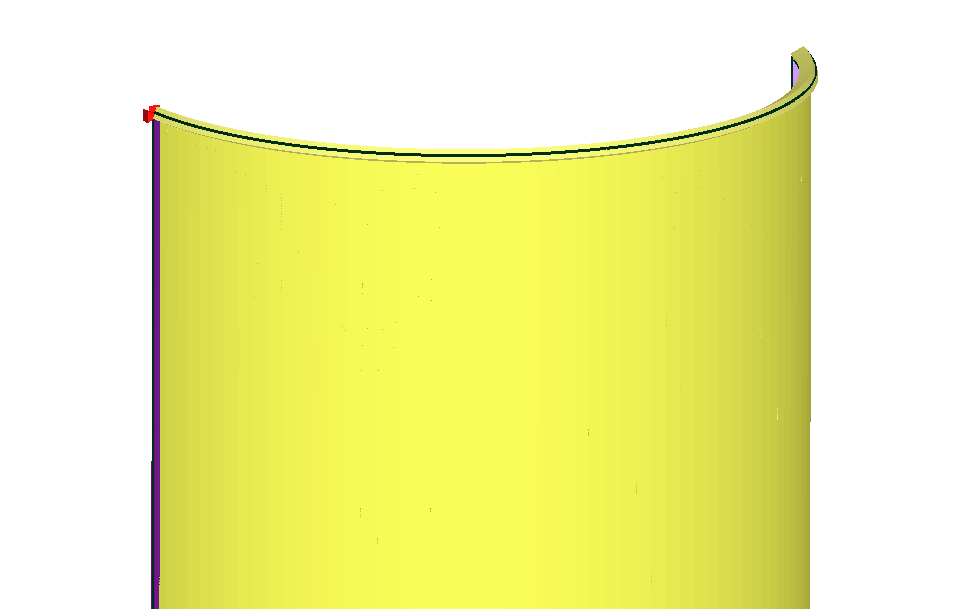
Mecway Shell Model:
I am trying to model a thin curved panel with a relatively thick outer frame. The assembly has a hinge interface on one side, and I am interested in how much deflection there is at the other side caused by the weight of the components. I tried making a shell model of the assembly, which worked well for linear analysis, but I am having a hard time getting it to solve when I transition to a nonlinear model which is needed due to the large deflections. I am using the elastic option for the bonded contact in the nonlinear case, and I am getting "nonpositive Jacobian determinant" in some of the elements of the main shell.
I've also tried replacing the frame components with solid bodies, but I have been getting errors with "Too many cutbacks" when I do this.
Any feedback, or suggestions would be greatly appreciated.
Thanks,
Paul
Overall Assembly Image:
Frame Image:
Mecway Shell Model:
Howdy, Stranger!
It looks like you're new here. If you want to get involved, click one of these buttons!
Comments
I wouldn't use bonded contact though. I'd extrude the frame mesh from the edges of the panel. That should be more reliable and easier to set up.
If convergence fails with "too many cutbacks", there might be rigid body motion. In particular, the bonded contacts might not have worked. Do modal vibration to look for 0Hz rigid body modes if they're not obvious.
Thanks for the quick response! I tried offsetting the frame pieces to account for the thickness. This worked with the straight side pieces, but when I added the curved top, I'm getting the Jacobian error again, I'm assuming it might be related to the fact that the shells are not perpendicular to each other. I used this angled surface to match the moments of inertia of the true geometry.
I am also trying to capture different material properties and densities between the frame, and the panel. Is there a way to do this with the mesh extrude method you are describing?
Section Properties:
Here it is with appropriate master and slave surfaces and it solves successfully.
With the extruded elements option, does breaking the elements out into a different component break the physical link between it and the component it came from? I tried this earlier today, but ended up having to redefine the mates again anyway or I would get rigid body motion.
Extrusion keeps the extruded elements connected to the original ones and components don't do anything in the solver except having materials associated with them.