Stuck?  support@mecway.com
support@mecway.com
Mecway
FEA
Contour plot -- Greyscale gradient seems wrong

Summary -- Greyscale gradient is significantly different than grayscale banded and is likely wrong.
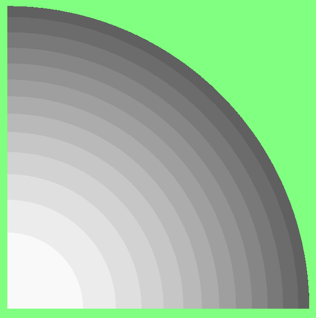
The attached model (H10a.liml) is a modal analysis of a 125 mm diameter cylinder (1/4 section). For mode 4 the following two images show the Displacement_z of the top surface (Horn_face) using a greyscale banded contour plot with 20 divisions. Note that the white area (highest displacement) extends along approximately 1/4 of the radial distance.
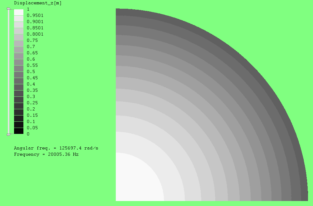
The average Displacement_z of the Horn_face can be calculated as follows. "\Solution\Surface integral" with F(X,Y,Z) = Displacement_z[m] and D = Horn_face gives 2018.
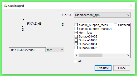
The area of the Horn_face is 3068 mm^2. Thus, the average Displacement_z is 2018/3068 = 0.658.
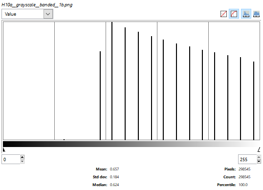
For confirmation, the average Displacement_z can also be determined by looking at the histogram of the banded greyscale (second image above).
The following two images show the Displacement_z of the Horn_face but using a greyscale gradient contour plot. Note that the white area now extends along approximately half of the radial distance.
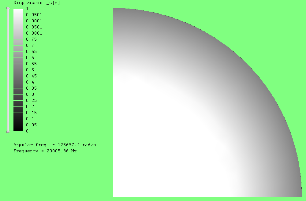
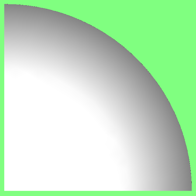
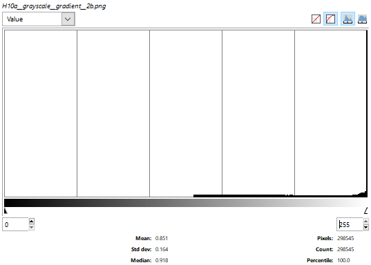
Then, using the above method for this contour plot, the mean histogram value is 0.851 -- too high compared to either the surface integral calculation (0.658) or the banded histogram (0.657). Thus, both visually and by histogram, the greyscale gradient seems wrong.
The attached model (H10a.liml) is a modal analysis of a 125 mm diameter cylinder (1/4 section). For mode 4 the following two images show the Displacement_z of the top surface (Horn_face) using a greyscale banded contour plot with 20 divisions. Note that the white area (highest displacement) extends along approximately 1/4 of the radial distance.
The average Displacement_z of the Horn_face can be calculated as follows. "\Solution\Surface integral" with F(X,Y,Z) = Displacement_z[m] and D = Horn_face gives 2018.
The area of the Horn_face is 3068 mm^2. Thus, the average Displacement_z is 2018/3068 = 0.658.
For confirmation, the average Displacement_z can also be determined by looking at the histogram of the banded greyscale (second image above).
- Load the image into GIMP.
- "\Select\Select by color" and click on the green.
- "\Select\Invert" to instead select the banded grayscale.
- "\Colors\Info\Histogram". The mean value is 0.657 (essentially the same as the above calculated value).
The following two images show the Displacement_z of the Horn_face but using a greyscale gradient contour plot. Note that the white area now extends along approximately half of the radial distance.
Then, using the above method for this contour plot, the mean histogram value is 0.851 -- too high compared to either the surface integral calculation (0.658) or the banded histogram (0.657). Thus, both visually and by histogram, the greyscale gradient seems wrong.
Howdy, Stranger!
It looks like you're new here. If you want to get involved, click one of these buttons!
Comments
For two homogeneous spheres with uniform solution the final tone is different too.
¿Shouldn’t the lighting effects be reserved for the modeling window?
The other light sources are there to reduce the extremes between lit and shaded areas, so that helps keep the colors more correct - when it's done right!
Thanks