Stuck?  support@mecway.com
support@mecway.com
Mecway
FEA
Analysis of carbon composite light aircraft wing using Mecway.

Here are some details of an FEA analysis of a carbon fibre composite light aircraft wing I did using Mecway. It took a bit of experimentation and figuring out but with some good help from Victor I was able to work out the stresses and size the wing structural components. I thought I would post this for anyone else who is using Mecway for similar sorts of analysis and im keen for any feedback or comments anyone has!
The mesh Geometry was based on this cad model I made
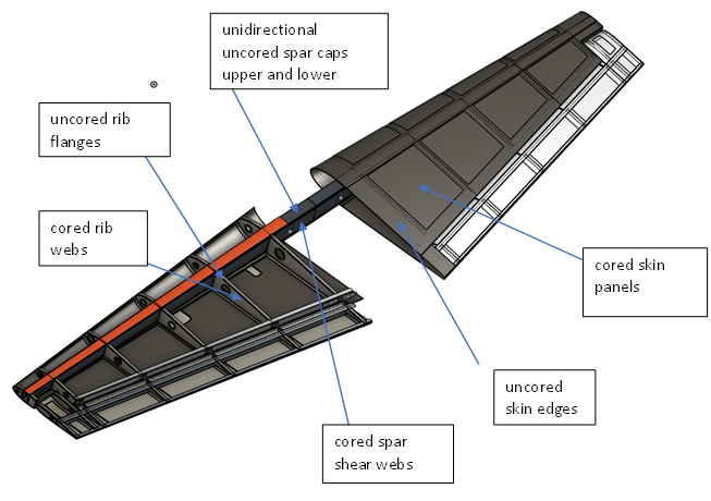
The wing is all Carbon fibre composite pre preg with nomex honeycomb cored panels in the wing ribs, spar shear webs and skins. The skins ribs and webs are Bidirectional pre preg carbon layed up over Nomex honey comb core material and the main spar also has a Cap flange made from unidirectional pre preg carbon fibre tape.
The mesh Geometry was based on this cad model I made
The wing is all Carbon fibre composite pre preg with nomex honeycomb cored panels in the wing ribs, spar shear webs and skins. The skins ribs and webs are Bidirectional pre preg carbon layed up over Nomex honey comb core material and the main spar also has a Cap flange made from unidirectional pre preg carbon fibre tape.
Howdy, Stranger!
It looks like you're new here. If you want to get involved, click one of these buttons!
Comments
I had to experiment a bit in order to generate a useable mesh. Originally I imported simplified geometry from the CAD model in the form of separate .step files then I auto meshed them and bonded them together using the mecway bonded contact function. The bonded contacts added lots of extra nodes and took a very long time to solve. The bonded contact joints pretty well corresponded to where the actual real life bonds in the wing were. I needed to add the aileron control surface to the wing mesh and this would have added a lot more bonded contact joints that would have taken much longer to solve. So I bit the bullet and decided to mesh the wing by hand
Wing mesh with bonded contact joints.
simplified stl file that forms the basis of wing mesh
I imported a simplified stl model from the cad soft ware deleted all the tri elements and meshed the model with quad elements by hand. It was a bit tedious but I ended up with this in the end
The large pink elements in the wing rib are about 1 inch square.
One of the complexities of analysing wings like this is getting the loads correct. If the loads aren’t realistic and accurate then the rest of the analysis will be meaningless. Deriving flight loads is more of an aeronautical engineering problem and as this is a FEA forum im not going to go too much into load factors lift coefficients and various different load cases but I will try and explain the way I have applied the loads to mesh.
Each of the various load cases can be reduced to a drag force, normal lift force and pitching moment all acting at the wing aerofoil ¼ chord line.
Wing loads acting on wing quarter chord line.
These lift, drag and pitching moments have a parabolic or elliptical spanwise distribution that reduces to zero at the wing tips.
I had generated lift and drag loads from other analysis plotted these and generated functions for lift and drag using a spread sheet. Mecway allows you to input pressure distributions as a function of x or y coordinates I tried this, but I couldn’t seem to get the loads to add up. The reaction loads I got were either way too high or too low suggesting that there was something wrong with the way I was inputting them. Eventually I ended up splitting the wing skin surfaces into 5 spanwise load areas likw below.
The green spar root area counts as a load application area to account for area buried in the fuselage. I applied a constant pressure load to each separate region based on the average of the spanwise lift drag and pitching moments for that segment of the wing span. The lift areas are split in the chordwise direction reflecting the triangular chordwise lift distributions recommended for some high angle load cases.
Pressure loads applied normal to upper surface of wing
Fwd view of wing showing lift load distribution applied to top surface of wing.
Mesh showing wing pitching moment distribution applied to wing ribs.
All elements used in this analysis were quad4 elements with a laminate material. A typical cored skin panel was input in the following way
The wing skins are made from Bidirectional carbon fibre prepreg layed up over nomex honeycomb core material. Each Bidirectional layer of pre preg is approximately 0.01 inches thick per ply and the nomex honeycomb core is 0.25in thick. This input represents 4 plies of bidirectional prepreg on each side of a 0.25in thick honey comb core sheet. The bi directional pre preg is oriented so that fibres are oriented +- 45 degrees to the spanwise long axis of the wing.
To get the correct wing stiffness all the various flanges and skin thicknesses need to be accounted for in the ply layup. To illustrate here is a cross section of the wing main spar below.
All the yellow material is Nomex honeycomb core material. The thicknesses and layups of the fwd and aft shear webs are the same and the spar is symmetrical top and bottom. The unidirectional main spar cap is surrounded on each side by the bidirectional shear web flanges.
Above is the area of the mesh representing the cad model of the spar above. The purple elements are the main spar cap elements and the layup was entered into mecway in the following manner
The top two lines represent 2 plies each of bi directional wing outer skin plies
The third line represents the uni directional core material oriented along the wing span
The lower 4 lines represent 3 plies each of bi directional main spar shear web material the uni directional spar caps are bonded to.
I used a The Tsai wu Failure criteria that is implemented in Mecway as the failure criteria for this analysis.
This is a screen grab of the Tsai Wu failure factor of safety with the minimum value of 2. The bright pink regions represent areas with a factor of safety greater than 15.
this is the wing tip deflection showing a max tip displacement of 2.4 in
The results I have obtained are pretty close to test data I have seen of similar wings made from similar materials.
I have also attached a simplified version of the mesh if anyone is interested in playing around with it
Cheers
Congratulations to you and of course Victor for the new release. We have a gem on our hands.
Did you 3d model this using fusion 360?
Do you have more information about this project on some other site? Could you tell where did you source the wing loading information?
Are you going to do some kind of flutter analysis? Do you think mecway is capable of doing that?
I modelled it using Onshape cad.
I dont have any other info on other sites yet. We are planning to build it though! . here are some pics of the complete aircraft
I analysed the the composite tail surfaces and tube steel fuselage truss using Mecway as well. I derived the flight loads my self using the FAA far23 appendix A loading guidlines.
I plan to do a flutter analysis of the control surfaces. I think mecway should be able to do it .....but i still have to figure that out!
Im new to Mecway and this post, among others, actually convinced me. Great work!
Just a question concerning the tsai wu creterion. As far as I know, the interaction coefficient should be between -.5 and 0. Why did you choose to use f12*=1?
https://help.autodesk.com/view/ACMPAN/2021/ENU/?guid=HELIUS-PFA-MANUAL-TSAI-WU-CRIT
Kind regards
kuhl
HI
Tsai wu failure theorem in this analysis is used to mainly get some idea of failure in the ribs and skins which are made up of bi directional carbon layups oriented at +-45 degrees to each elements U and V axes. i wasnt sure which interaction coefficient to use at first but i found this derviation of the Tsai Wu theorem on you tube.
which says that for practical purposes as long as it is within physical limits it doesnt matter which value you choose. i ran a few test cases with values between 0 and 1 and couldnt see any difference in the safety factor when i changed it. so i just left it at 1.
The uniaxial carbon fibre spar caps are the primary load path that keeps the aircraft in the air and these tensile and compressive stresses are checked directly against published material spec sheet allowables with a factor of safety of 2 which is industry standard for composite aircraft.
The Wing Loads are Elliptical and it's good to get an idea of where the loads vary to match where the layers of Uni Vary in the Spar, a much more natural load spread. Remember to go a little past that load with each layer. JIM Marske uses an even spread he feels it's a smoother transition for his Gliders.
Lift = weight, so include your HT download into your weight divide that weight into the Length at every inch of the half ellipse allow only 45% in the Cockpit area and include that lift into the Wing area. Add up all the numbers to see if the match your overall weight.
Your 4 layers of Carbon Bid at +/- 45 deg may make the wing too stiff and more than necessarily heavy, I have opted for 2 x 8.8 oz with a deflection of around 12". Remembering Carbon is very stiff.
Safety factor 2 YES! and I used G factor of 6 (Aerobatic), although a hard landing can be up to 6.
Hope that helps someone.
Lendo.
The comment to allow only 45% lift (in the elliptical lift) for the Cockpit area, is from M. Sadraey, I then transfer the additional 55% to the Wing past Fuselage mount point. This additional load is spread elliptically, as does the HT download.
Hope that helps.
Lendo