Stuck?  support@mecway.com
support@mecway.com
Mecway
FEA
Spider Beams API Help

I find Spider Beams very useful for the stuff I model -- load transfer diaphrams at shell/line element interface, bolthead/washer, etc.
Thought I would give the API a whirl to automate the drawing process. Cut&Pasted from some of the fine code contributions available.
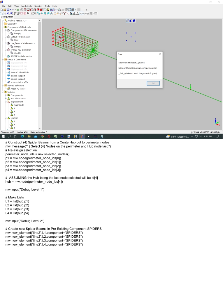
But I fail! The problem seems to be how I populate the List. I either get a "Casting" error, or an "_init_()" error. Directly entering node numbers into the mw.new_element() command will draw a beam correctly, so I think I'm nearly there.
Secondly, I would like to pause the program during the input phase so I can screen-pick the Hub center node.
Any help for an old Fortran guy?

Howdy, Stranger!
It looks like you're new here. If you want to get involved, click one of these buttons!
Comments
--------------------------------------------
def mod_node(nodes, value):
for point in nodes:
mw.set_node_x(point, value)
usr_selected_nodes=mw.selected_nodes()
ref_node= mw.node(usr_selected_nodes[0])
modified_nodes=len(usr_selected_nodes) - 1
if len(usr_selected_nodes) > 0:
mod_node(usr_selected_nodes, ref_node.x)
mw.message(str(modified_nodes) + " nodes will be modified")
else:
mw.message("No nodes selected.")
Not sure if this is the same as a spider beam (new to me) but If it is, it could be done "easily" and maybe could be translated into your API function.
Unfortunately, I’m very bad programing and I can’t help in that sense.
It is based in the other day small variation of JohnM’s method to automesh2D.
The sequence would be :
Selection of nodes to connect.
Nodes small extrusion.
Asign new lines to new element (¿Spider beams?)
Select new nodes.
New Nodes Merge “in mase”.
The merge radius should be very large to merge all the nodes at once. Root node seems to go inbetween.
Does this has any sense??¿?
Here's version 2. Not robust enough for the Python Script Folder yet. Gotta make it variable number of nodes. Python programmers -- have at it.
Note: Selecting all nodes of interest, then CTRL unpick/re-pick the Hub center DOES make it the last node in the list.
@disla: I was just thinking of the recent automesh2D post as well! That method works well on endfaces. The Spider method seems more general, as it is pt.-to-pt. Works quickly with Named Ranges? Let's RACE them. (Cool graphic, btw. That could sit on my desk.)
Now only left to know how to reference to the last node of the array of selected nodes, I will investigate this tonight, looks an interesting and usefull problem.
About your spider problem, what I will try to do is
1) Create an empty component called "spider1" by hand (as far as I know there is no way to make it by script) with a beam material (very small diameter and high stifffness)
2) Select all the nodes of the spider, with the least being the reference node
3) Try to create a script that create beams element between the reference node and the others, and put this new elements in component "spider1". That should be made with a loop running trough all the array of selected nodes
Well done and thanks for sharing!!. I can see you managed to find the way to get it work.
As these spiders are new to me , I have been doing some readings and tests and if I understood it correctly literature differentiate between :
RBE2 designed to transfer displacement. Kind of Node Surface Coupling Kinematic (deprecated).
RBE3 designed to transfer load from one body to the other. I guess that would be the Node Surface Coupling Distributing (deprecated).
¿Would this spider beam elements be like an adjustable RBE2/3 ?
Apart from the amount of load transferred I can see that the shape and distribution of this load is adjustable depending on the stiffness of the beam elements.
¿Which would be in your opinion the recommended values?.
Sergio suggests thin beams with very high stiffness. ¿Do superhigh stifness transform the spider from RBE3 to RBE2 ¿?
Regards
Disla
https://we.tl/t-flrVw7QWIb
To begin, employing an array of hyper-stiff beam elements, what I've called Spider Beams, is NOT the same as RBE2/RBE3 elements. Those elements use displacement constraint functions in ways I don't fully understand, and weren't directly available in MW at the time. Since I'm not proficient w/CCX, my use of Line elements was a sophomoric effort at transferring forces/moments across junctions of differing element types. The benefit was obvious -- save the node budget using Line elements to model a frame structure, then Shells to focus on a particular joint. (See pic, along with a couple slides of static bending comparison tests.)
Apologize for the name confusion, disla. It seems Spider "elements" are a term referring to RBE2's. We can call my script Dandelion if it suits.
I've achieved acceptable results within approx. 3% of theory w/out RBE2's, which seem reasonable. However, my testing has been confined to long beams. I wonder if disparities are amplified between the methods in a less slender application(?) Seems that a square PL constrained 2-sides & w/ a center hole is a litmus test of sorts. Can anyone familiar with RBE's run the test shown below to compare RBE2/3 with my answers? Kind of would like to know whether the hyper-stiff Spider method has merit on a smaller scale. (Display scale locked to x 500).
Thanks for all the help.
Good news for your Dandelion.
If you use Springs instead of beams , the square plate with hole delivers exactly the same result as Rigid body.
The picture shows Node Surface Coupling RIGID against Dandelion using Beams , using Truss and finally using Springs.
Last picture on the lower right corner shows the Dandelion with springs using the internal solver.
Edited: With ccx it is needed to offset the center node from the common plane.
Connection between a beam and a shell is rigid although they both have rotational degrees of freedom.
When connected to the through thickness shell side , it don’t allow that section to rotate properly during the deformation locking the full development of the deformed surface.
Well, I wanted to see what shapes other software would produce using RBE2 & RBE3 elements. Drug out the old Nastran stuff. Felt like trudging through mud compared to the ease of modeling with Mecway (cheers, Victor.)
The screenshots show a distinctive shape when using RBE2 or RBE3 for this model (Mag. Factor x 500). Nastran also produced the radius transition for RBE2 at the top, and the scalloped look for RBE3. No hard flat-tops. I'm wary to report the vM stresses because I don't think I was comparing the same mesh densities, also stress risers at connection points, also linear quads vs. 2nd order. As it stands, deflection was within 3%, von Mises
was within 10%.EDIT 8/11/22: Went back & compared results using identical mesh density and degree of element order. Results for both displacement and stress between Nastran RBE2 and Mecway were very close, but I'll quote the more comfortable margin of 3% difference. Posting updated Spiders.py script to Forum Script Folder.