Stuck?  support@mecway.com
support@mecway.com
Mecway
FEA
Analysing sheet metal structures
Hi there.
I'm trying to do some analysis on the chassis of one of our cars, which are made from sheetmetal and I'm having major difficulties.
From Solidworks, I have removed all holes and irrelevant fillets and then I can export the geometry as a solid, mid-section surface or the surface of either side of the sheet metal features. I don't believe that my computer will run with the amount of elements needed to properly model it as a solid so I've exported them as surfaces.
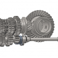
Here's a screenshot of the whole assembly just to peak your curiosity.
I have run a test simulation with single sheets and it works but the full assembly won't run.
One issue is the error "*ERROR in gen3dnor: size of estimated shell normal in node 977 element 76887 is smaller than 1.e-10"
I have been using the element list to seek out which part has the faulty elements and have deleted the parts until it would no longer give this error. Another error message has appeared:
"*ERROR in e_c3d: nonpositive jacobian determinant in element 41832 " and when I click "select elements", all of the elements that are part of a contact is shown.
I suspect that the issue lies with the bonded contacts and possibly with the fact that "nodes on the slave surface is moved in a strain-free way to lie on the master surface" as stated in the manual.pdf.
My question is now if the parts should be exported as midsurfaces so the master and slave are spaced apart or if they should be exported as the surface of a face so the surfaces are touching before meshing?
If anyone has any other suggestions of how to best work with shells or sheet metal parts, I'm all ears.
Best regards,
Sebastian
I'm trying to do some analysis on the chassis of one of our cars, which are made from sheetmetal and I'm having major difficulties.
From Solidworks, I have removed all holes and irrelevant fillets and then I can export the geometry as a solid, mid-section surface or the surface of either side of the sheet metal features. I don't believe that my computer will run with the amount of elements needed to properly model it as a solid so I've exported them as surfaces.
Here's a screenshot of the whole assembly just to peak your curiosity.
I have run a test simulation with single sheets and it works but the full assembly won't run.
One issue is the error "*ERROR in gen3dnor: size of estimated shell normal in node 977 element 76887 is smaller than 1.e-10"
I have been using the element list to seek out which part has the faulty elements and have deleted the parts until it would no longer give this error. Another error message has appeared:
"*ERROR in e_c3d: nonpositive jacobian determinant in element 41832 " and when I click "select elements", all of the elements that are part of a contact is shown.
I suspect that the issue lies with the bonded contacts and possibly with the fact that "nodes on the slave surface is moved in a strain-free way to lie on the master surface" as stated in the manual.pdf.
My question is now if the parts should be exported as midsurfaces so the master and slave are spaced apart or if they should be exported as the surface of a face so the surfaces are touching before meshing?
If anyone has any other suggestions of how to best work with shells or sheet metal parts, I'm all ears.
Best regards,
Sebastian
Howdy, Stranger!
It looks like you're new here. If you want to get involved, click one of these buttons!
Comments
Another point is that as the shell elements will be expanded, in the radius zone if the radius is omitted, or is to small with respect of the thikness, this elements could intercept itself with the expansion, that could lead also to errors.
A third note, at a first analisys I would use biger elements, at least in the flat areas away from radius, TIE and other geometric discontinuities. If you will fail, do it in the less time at least until you tune the BC.
I understand you have run the static problem without contacts and without loads just to check the stiffness matrix assembles correctly. ¿Isn’t it?
¿Did you activate "split periodic faces" when exporting from Solidworks?. Maybe the problem comes from wrong Slave Master faces mapping.
I’m referring to that "Faces do not map to proper surfaces" post.
I would add contacts one by one without any load (after reducing the number of elements if possible as Sergio suggest.)
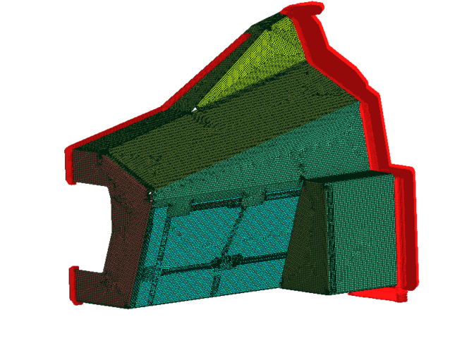
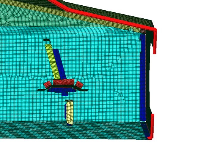
Now I've gotten an analysis to run with only 3 parts and can see that it is the nodes of the 3D mesh from CCX that is being moved and have contacts applied to and not the surface mesh, which does indeed distort the elements significantly unless corrected for by shell offset.
Also, it seems that some stresses can arise when elements are deformed by having some nodes including midside nodes moved to contact while some corner nodes are not moved to contact due to overhanging the contact zone.
@disla Yes, my first step is to run without loads to see that it assembles, runs and gives results that are free of stress. I did not check "Split periodic faces" in solidworks as I only do that as a last resort as it completely changes the number of faces and thus messes up any selections I've made in Mecway which refer to the face numbering of the STEP file. I have had wierd issues however where a faulty face was fixed by moving a trimming 1mm, so solidworks aren't completely sane today either.
Adding contacts one by one as proposed by Disla was what allowed me to have a model that would run and It seems that the conclusion just is that the midplanes are what should be exported from Solidworks unless one want to compensate with shell offsets.
I've finally finished my analysis. It was a bit frustrating but turned out good enough in the end. Among the issues that persist after using only mid-surfaces turned out to be some sloppy CAD modelling from my predecessor so some faces were only almost touching and not parallel, so no matter what I did in Mecway, the elements would still get deformed to the point that they had several thousands MPa of stress without any load. Luckily, the problematic geometry was sufficiently far away from my area of interest that I feel confident in the result being approximately good enough but I really have to tidy that up and revisit the analysis when I have a slower period.