Stuck?  support@mecway.com
support@mecway.com
Mecway
FEA
1d beam problem

Hello,
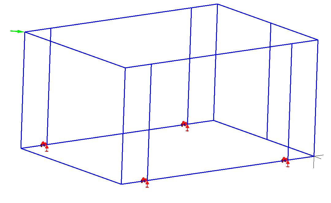
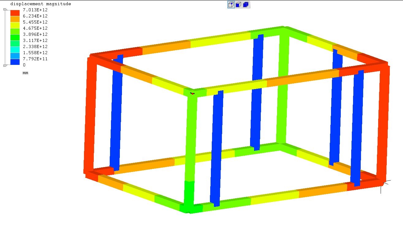
As a total beginner i have a problem , here is the steel cage i want to test, all profiles are 100x100x5 steel rectangular tubes with the 4 fixed BC on nodes and 1 load the results give me large displacements , for me it looks like the lines are somehow loose and not connected with each other, how do i fix this?
Thanks in advance
Mike
Howdy, Stranger!
It looks like you're new here. If you want to get involved, click one of these buttons!
Comments
I did'nt find a way to export a 3d frame with Solidedge or Alibre Atom, and read it in Salome or Mecway directly.