Stuck?  support@mecway.com
support@mecway.com
Mecway
FEA
Ccx 18. Beam under compresion Static 3D

Hi,
I'have observed weird results on a beam under compression.
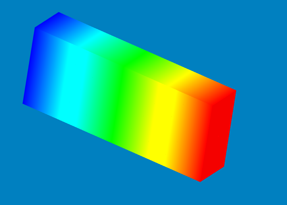
When calculating with the internal solver everything is smooth and the beam behaves as expected.
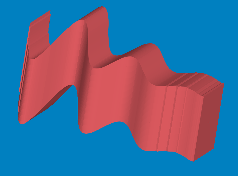
When using calculix_2.18\ccx_dynamic.exe both pardiso and PAstix gives weird results.
¿May i have some missing dll. Does it happen to someone else?.
Thanks
I'have observed weird results on a beam under compression.
When calculating with the internal solver everything is smooth and the beam behaves as expected.
When using calculix_2.18\ccx_dynamic.exe both pardiso and PAstix gives weird results.
¿May i have some missing dll. Does it happen to someone else?.
Thanks
Howdy, Stranger!
It looks like you're new here. If you want to get involved, click one of these buttons!
Comments
I have also posted in the ccx forum as it clearly seems a ccx issue.
However, CCX beams do have a bunch of problems. From the Mecway manual:
"The CCX solver (2.17) has some bugs with beam elements. Non-zero displacement constraints on beams can cause incorrect stress, and constrained rotational DOFs can cause incorrect external force. Mecway will show a warning in the outline tree if the conditions for these bugs are met."
looking at the results more, though, shows the fixed bc isn't applied right either. one end of the expanded elements is free to rotate. it doesn't look like any bc was applied to some of the nodes. even weirder is animating the results. then it looks like the fixed displacement was moved to the middle and the ends were free to rotate. however, there are no nodes at the middle. so this is really weird. it still makes you wonder what it did to the force load. seems like a lot of issues with the shell expansion and bc application.
ps; tested with version ccx 2.18. also, it's odd how the pardiso and pastix results are different in this case. they seem to be different whether truss is on or not. i attached your file with slight changes for debugging. mecway solver has the same result whether truss is on or not. also, the mecway result also seems to make sense, for the load applied.
note; i'm not sure if the elements were expanded to shells or solids. i said shell above, thinking of taking beams to shells. however, ccx might have went from beams to solids. i didn't see a way of checking what the final elements were.
update; if you use a beam element and change your constraint to a fixed bc, then all the solvers get close to the same result. that may be the way to go here.
That said, it's a curiosity the internal solver produces the same results with only 3-displacements constrained that CCX does with a fully fixed base.
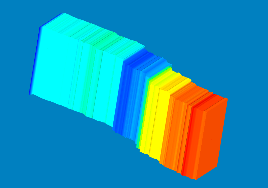
Confirm the two-node truss elements also. Any further resolution between endpoints yields weird graphical zig-zags, although the reaction forces remain correct.
I have also receive response from the Calculix forum.
"above example are for truss element, so it does not required mesh to be refined. only use one element mesh betwen each joint of connected members. Spliting and refining mesh may cause stability problem and spurious movement since each element end nodes become hinged".
That's in line with the Mecway Manual that says truss do not have bending (each node only has translational degrees of freedom) . By refining I was doing things worst.
By other hand. I have build and refine a truss with a mass at the end expecting it to behave as a pendulumm (chain) but it fails. Also changing the force direction on the previous file aslo fails so it should not be exactly a hinged connection.