Frequency response analysis - manually adjusting Dynamic Response
Victor --
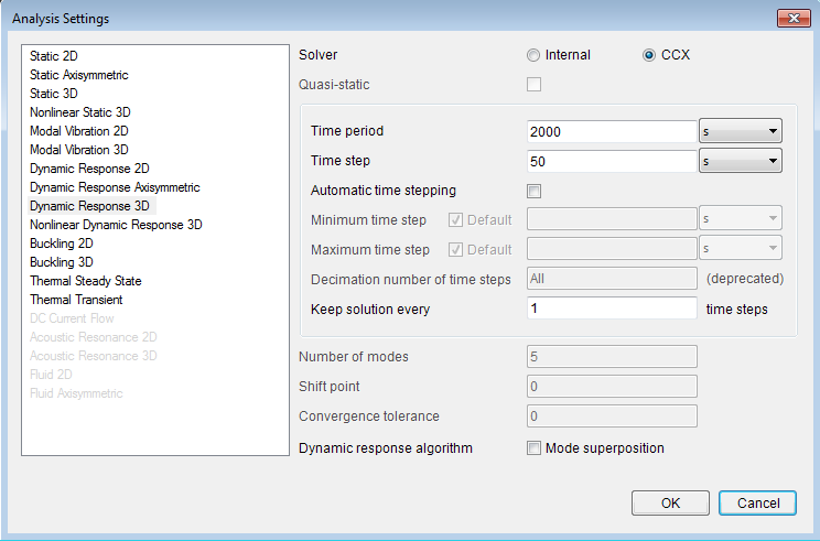
I'm continuing our discussion from here (https://mecway.com/forum/discussion/900/improvement-suggestions/p2) so that the "Improvement suggestions" thread doesn't get sidetracked. Your comment, "It turns out you can do frequency response by manually specifying the CCX cards. and interpreting time as frequency in the loads and solution."
When I have previously run frequency response analysis (FRA) with Autodesk, there were 3 outputs at each frequency -- an in-phase displacement, a 90 degree out-of-phase displacement, and a displacement magnitude (combined in-phase and out-of-phase amplitudes). For your model (attached below), are these the D1, D2, and D3 displacements (i.e., D1 = in-phase, D2 = out-of-phase, D3 = magnitude)?
Also, I notice that there many small timesteps but also some large timesteps -- e.g., going from 242.3 sec to 412.9 sec. I don't know if this is how the custom model definition was set up (below, which I'm not familiar with) or whether it's an anomaly.
*STEP
*FREQUENCY,STORAGE=YES
30
*END STEP
*STEP
*STEADY STATE DYNAMICS
100, 2000
*MODAL DAMPING,RAYLEIGH
,,5000.,0.
Don C.

Howdy, Stranger!
It looks like you're new here. If you want to get involved, click one of these buttons!

Comments
I'm not sure what to do about the irregular frequency spacing. It seems to be done automatically by CCX. Some of them correspond exactly to the natural frequency modes so perhaps if you use more modes (30 in this example), you'll get more frequencies.