Distribuiting coupling

I found an interesting example how to apply DCOUP3D element to join cylindrical surface.


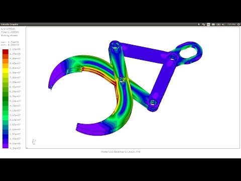
I replicated this example in a more simple model trying different types of mesh:

Tetrahedrons C3D10, Hexahedron C3D20-C3D8 and Hexahedron with reduced integration C3D8R.
The results on attached pictures. So is possible to see how C3D8R underestimates the stress YY due to bending moment.

Comments

  • Wrong screencapture...the right one

  • Thanks Andrea. At some point, I'll do a bunch of experiments and research into this. From this example, it looks like an optimization that's not very important since you could just refine the mesh a little more or use quadratic elements in bending dominated cases where reduced integration is more accurate/efficient.
  • You can add to element library C3D8R, C3D20R and the others reduced integration elements relative to plain stress, plain strain, axisymmetric...For the solver is only to read a letter R after the name of the elements.

    User could be free to choose which element is better relative to the on going study .

    But my focus was how to  use DCOUP3D elements to join two cylindrical surfaces. The result is that the axes of the holes are constrained one with the other (same ux, uy, uz) but the two surfaces are free to rotate indipendent. So is like a hinge joint.
    Same strategy can be utilized to assign a load or displacements to a node set through  the immaterial node of the DCOUP3D element


  • edited January 2017
    Just a question, using a RIGID BODY between a center node and the surfaces of the holes would create the same condition? I use very often RIGID BODY, but never DCOUP3D.

    By the way, would be nice to have both (RIGID BODY and DCOUP3D) available on Mecway interface, even with a graphical representation of the lines uning the nodes and the reference point). This things help a lot when you need to show or explain the bondary conditions to a non experienced client.

    Regards
  • Andrea, what's holding me up is how to do it appropriately. If there's just an extra option for every element to use reduced integration then it will be an obstacle for more people than it helps. Whenever something doesn't work, it'll be tempting to try to change that option just in case. It's also bad because everyone will see it and have to make a decision about how to set it when 99% of the time a sensible default will be sufficient. So at some stage I hope to properly investigate this and put in useful options that are convenient for when they're needed but not too distracting when they're not. In the mean time, there's the global labs option.

    For DCOUP3D, I intend to add some features to generate that, including calculating the node weights. It looks like you're already using CalculiX Launcher http://calculixforwin.blogspot.com/2015/05/calculix-launcher.html which generates connections like this. So for anyone else making mechanisms, that might be a good choice.


  • About Reduced integration elements I also have to find more information. Interesting is the post of Kwip about "superconvergent" behavior.

    About Calculixforwin I downloaded it because has UNICAL converter inside but the wizard doesn't run under Windows. The autor produced a very interesting tutorials about Salome mesh module and Calculix.

    If you want introduce DCOUP3D to simulate hinge you must also improve the *Equation card and *TRANSFORM card. In fact to simulate a fixed hinge axis the fast way is to use the transformation in a local cylindrical coordinates.

    By the way CrunchiX manual puts the attention over the number of nodes:

    "The more nodes are
    contained in the distributing coupling condition the longer the equation. This
    leads to a large, fully populated submatrix in the system of equations leading
    to long solution times. Therefore, it is recommended not to include more than
    maybe 50 nodes in a distributing coupling condition."

    Nowadays is maybe possible use more nodes because of more power of calculus


  • Hi Sergio!

    I tried to apply RB to the model but CCX goes in crash. I attach liml file to check.
    I you have time check the RB applied on CCX cuxtom model definition.

    I tried to apply to ELSET, to considering ROT NODE but dosen't run.

    Maybe the problem is in Equation card to tie the two ref points
  • Yes...good Idea Sergio.
    The problem is CCX under Windows because I send the inp file for solving under Linux and the model is correct.
    There is difference between displacements and stress relative to the other model (with DCOUP3D).

    Soo I will install Oracle VM to try under Linux.

  • This is the model solved using only RIGID BODY, but as we can see in the holes there are "radial" growing, this is something that I have seen in the past using this method and never find a way to solve or at least understand. If the nodes of the holes are attached to the center point by means of the rigid body, why they have this deformation?

    I have changed the vertical arm from the Andrea's model in order to have a perfect simmetric model (otherwise I would have to apply some unreal boundary conditions to restric the lateral deformation as the two arms are not in the same plane)

    Regards
  • I will try to reproduce using DCOUP3D and see what happens in the holes. This growing is small, we are seeing the model scaled almost x2300, but should be zero.
  • I have removed one rigid body at one hole, so now the horizontal bar is free to rotate, and change the load for a displacement (20mm in vertical direction), to see if increasing the rotation this growing in the holes remains or increase also. If we look the deformated model without scaling, looks like that there is no deformation on the hole, but if we add a scaling (2x), we see again this growing. Could it be a matter of the postprocessor???


    Regards
  • Don't worry...its only post-processing's issue. Radial displacements are null. I try to explain.
    In the real case nodes must move over the circumference. Postprocessor moves the nodes along the tangent. So graphically they appears on circunference of higher diameter. (It's a consequence of the linear analysis -> small displacements)

    The worst case is in torsion of a long cylinder or pipe. This effect becomes enormous like a funnel.


  • Pipe with Rigid Body to apply constrants and torsion. Follow a radial displacements (CGX post processor)


  • Andrea, can you provide me the .liml model using the DCOUP3D feature?  I would like to look into it.  Thanks!
  • VMHVMH
    edited March 2017
    .
  • Victor, can you help me with an example of using dcoup3d using Mecway custom model option? I've been trying to set it up but couldnt.
  • Thanks Victor,  I was trying to figure out how to setup DCOUP3D element to join cylindrical surface, same as the screenshot Andrea originally posted without using rigid body.
  • Hi!
    I attach the liml file relative to the study with C3D20 elements. You can change elements type in Mecway if you want.

    Regards, Andrea
  • Andrea, thanks alot!
  • Thanks too Andrea. Just a warning - it doesn't capture bending and twisting moments that would exist with an offset joint like this. Sergio corrected that above by making it symmetric, although with rigid body instead of distributing coupling.

    This seems to be a danger with distributing coupling (and rigid body?) if the reference node isn't at the centroid of the other nodes. I expect you could correct for it with clever selection of the node weights.

    This picture compares Andrea's model to the same but with distributing coupling replaced by merging adjacent nodes of the two parts.
  • Victor, thanks for pointing it out.  I'm doing several tests to understand it.
  • The aim using DCOUP is to obtain a 2D hinge. Using RB instead DCOUP the result shows bending (see attached picture...the model was created with hurry). I choose this asymmetric model for this. My interest is to simulate pantograph structures but is more fast using RB and locking the displacements on the direction normal to the plane (to obtain 2D behaviuor). Obviously there are also more efficient ways.

    I have to investigate more about 3DCOUP but now I haven't time

    Attention! I had to solve the model under Linux because the combination of *EQUATION and *RIGID BODY cards makes CCX crash. I posted about this problem also into CCX forum. So, as I wrote some time ago, is better to solve under linux above all for buckling analysis. In fact under Win buckling analysis shows vey often strange eigenvalues which are not acceptable. Under Linux the solution is correct

  • Thanks Adrea!

    Sergio,
    I have a question for your approach using RB. For the middle connection holes, all of the node set was set to a single node. This mean the parts are rigidly connected to each other and not able to rotate? Is there a way to let the parts able to rotate independently usinf RB approach? Probably using conincident nodes and RB's but how to tie those nodes together and restrain the displacements and free the rotations? Thanks
  • You could define a different RB for each part (guess that you will need four reference nodes in the same point... a little tricky to manage in Mecway), But now you need to link both reference points (those that control displacement, not rotation) in somewhere, maybe using equations or something like that.

    In this case that the vertical arm has two zones, maybe could be defined two RB for the vertical, and one for the horizontal. Then add a beam element (circular section) to join all the three center nodes...will be funny to see it ;-)
  • After thinking a little guess that will be better to model the pin as a solid and use contact, otherwise RB will artificially restringe the posibility of deformation on the holes.
  • Sergio, thanks for your responses
  • Follow CCX forum because M. Kraska is studing this kind of input card. So I think that will be more clear
Sign In or Register to comment.

Howdy, Stranger!

It looks like you're new here. If you want to get involved, click one of these buttons!