Stuck?  support@mecway.com
support@mecway.com
Mecway
FEA
3-way surface intersection & fixing edges of surfaces.

Hello I am a new user figuring things out.
What is the most convenient way to deal with this work flow?
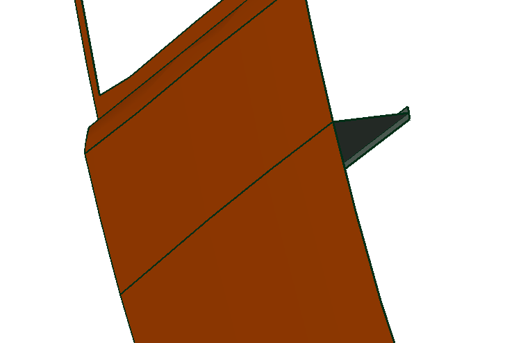
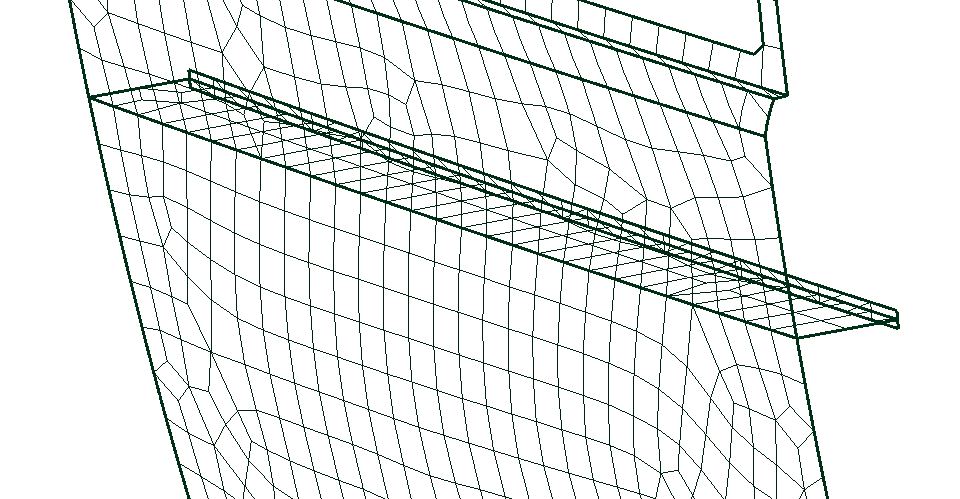
A 3-way intersection between surfaces, they need to be different components to have different materials, so I import them seperately. I copy mesh parameters and mesh them together, the meshes visually line up, but the result is they are not connected?
i found I can merge nodes by proximity, is that the only method?
What is the most convenient way to deal with this work flow?
A 3-way intersection between surfaces, they need to be different components to have different materials, so I import them seperately. I copy mesh parameters and mesh them together, the meshes visually line up, but the result is they are not connected?
i found I can merge nodes by proximity, is that the only method?
Howdy, Stranger!
It looks like you're new here. If you want to get involved, click one of these buttons!
Comments
-For simple stiffeners you could also try to use manual mesh generation by extrusion.
-*Tie should also work here.
Regards
the merge tolerance till they merge. If u upload the file I will happily have a quick look
Is there a way to select edges before meshing, to inform the mesher that these need to be joined, or at least have the same number of nodes/spacing, so that I can reliably merge nodes after the meshing?
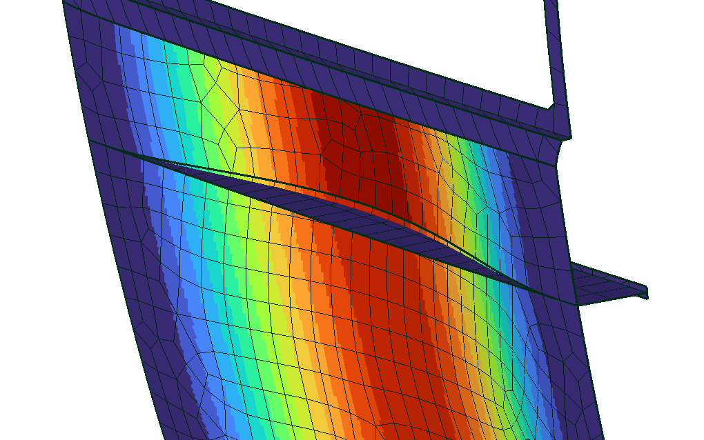
I'm wanting to run FEA on a yacht, with a large number of different sized panels, bulkheads and stiffeners all connected.
for now I am just practising on this simple panel with a stiffener to get a good workflow before I attempt the larger yacht structure.
I have attached an STP file.
Ansys has shared topology. Altair Hypermesh has seam welds. The best I’ve found in FOSS world is that Gmsh can take compulsory nodes as an input to a mesh command, so you can mesh part A first and give the coincident edge nodes in the mesh command for part B then merge at zero distance. Gets a bit icky where element edges are far from parallel.
Doing the merging by hand or using tie is ok… until you have a chassis of hundreds of parts and you need to iteratively design.
I was just commenting on the method I have tested to get around the problem for myself.
I recall some years ago Sergio found the way to create a compound part in GMESH before meshing so the mesh was conformal in between the different parts.
Maybe it could work here.
https://mecway.com/forum/discussion/comment/3956#Comment_3956
EDITED: Sorry my browser didn't update last posts. I think it is the same solution proposed by Victor. Seems it generates some surfaces dublicated isn't it.
Yes I work in Rhino, which is less anal about tolerances than other CAD software, though you I can dial up the tolerance before export.
Above was just a simple example, I am wanting to do FEA on entire yacht structures where this problem repeats across hundreds of components. So my workflow which I find to be working is to do the meshing in Rhino, then using a Rhino Python script to write the rhino mesh direct to a new .liml file.
A big advantage for me, as all the structures are composite and element orientation is critical. Is that I can control the element orientation inside rhino through UV mapping, so its all written to the liml file
And being a daily Rhino user for years, its much quicker for me to orient UV maps, perform mesh cleanup, refinement, merge nodes etc. before export, than it is to do inside the Mecway UI.
so far so good...