Stuck?  support@mecway.com
support@mecway.com
Mecway
FEA
Contact with Shells

Hi there, i am struggling with convergence of attached shell-based model. The plate normals are directing towards each other, correct gap between elements based on thier thickness, small incremental loads etc, but still unable to converge. 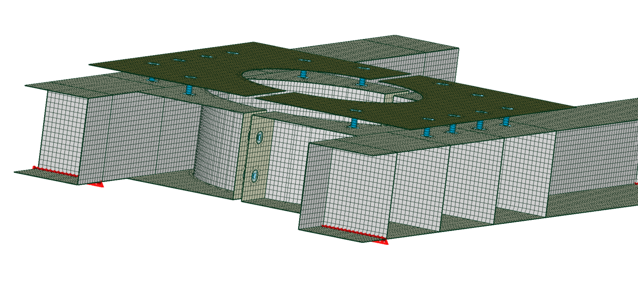
Howdy, Stranger!
It looks like you're new here. If you want to get involved, click one of these buttons!
Comments
I have had some success in the past using simply solid bolts so I had a quick play with them in your model, I stuck with the shell structure, removed all the RB3 couplings and setting up some solid bolts. I used symmetry with a compression only interface where the two halves meet at the horizontal bolt junction. (i'm not exactly sure what this may miss out on, but it certain was much quicker to run).
I played around with pretensionng the bolts with the pretension function and shrinking the bolts with thermal contraction -I preferred the later but may be i was not using the pretension correctly.
I'm not sure I set up the contacts correctly,
but with a little cheating (soft springs to get round the rigid body issues and some controls to help convergence) I got the analysis to run to a deflection of just over 3.3 mm at the edge of the circular hole in the thick plate on top. From my potentially very inaccurate model this seems to be a rim load of about 105 KN on the full model
with the convergence parameters relaxed this takes about 30 mins to solve
The issue I think it's one of the bolts. If one runs the analysis without the quasistatic option, it completes without issues.
Fix those opposite normals and with a simply suported BC VM drops to 49 MPa. I think averaging on shells could be is affected showing spiky VM junctions.
Keep an eye on the conctact clearance.
EDITED (95 MPa) without Output 2D
One aspect of not using a quasistatic approach in complex scenario like this gets me a little confused is the sequence of the loading. In the real world bolt pretension is applied before the load is applied. If the sequence were reversed I expect the results would be different. When the analysis is bundled together I wonder if, in this case, the end result is different.
I'm missing 137 Kg in the overall vertical reaction. I'm using some springs in the support to separate External loads from reactions and measure properly.I measure reaction at the spring base. I think some couplings could be interacting with the contacts generating some over constrain. It would be better to exclude the coupling from the contact definition. Not sure yet where those kg are.
With nonlinear, the overall reaction force matches with a deviation of virtually zero.
-To fix opposite normals I have imposed an overall orientation and then inspect the model to see which normals are still pointing in the "opposite direction".
The monitor provides some node numbers which can help to locate the areas, but correction was done manually. Select those surfaces and invert them.
-By Simply supported I mean releasing the constrain in X direction on one side so it can slide in that direction.
-Supporting the piece on a set of springs away from the piece is to measure reactions properly. Your model has distributed load (g) and it would be included in the reaction. Springs doesn't have mass so you can measure there without that risk.
They have been generated manually extruding the nodes into lines.
-Regarding pretension. There is a lot of interest on pretension around. I have applied it full at the beginning and it converge well.