Stuck?  support@mecway.com
support@mecway.com
Mecway
FEA
Mecway mesh - extraneous surface lines at bottom of drilled hole

I have a cylinder (1/2 3D) with a 12mm dia hole at the centerline. This hole ends in a cone which approximates how the hole would be machined with a drill bit. The model was constructed in FreeCAD 1.0.0.
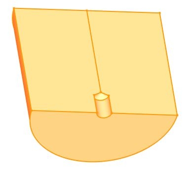
Using the FreeCAD Netgen mesher with the max element size = 10 mm but other defaults, the hole has a nice, uniform mesh.
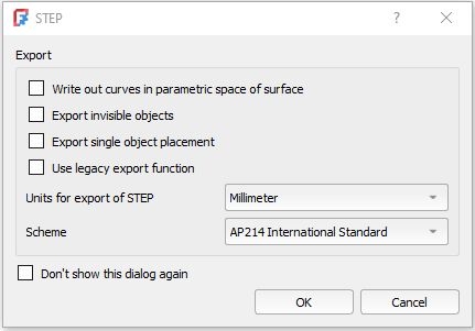
The FreeCAD unmeshed model was then exported as a step file. Note that the first item ("Write out curves in parametric space") is not checked here. (This is normally checked by default but leads to extra Mecway nodes at the cone point.)
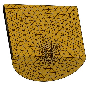
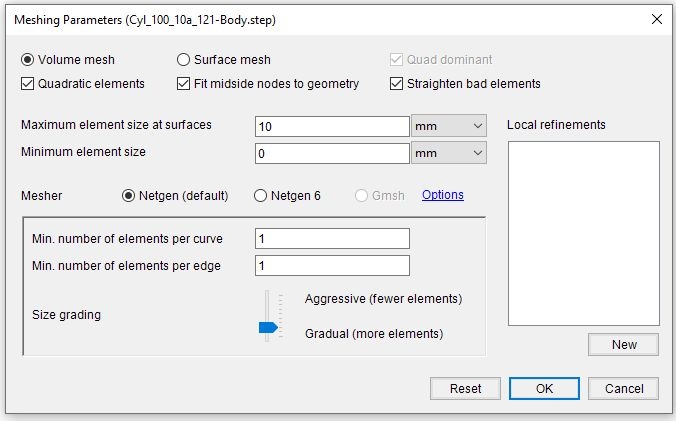
This step file was then imported into Mecway. The following mesh settings were used for this topic (not necessarily optimum). The intent was to later manually refine the hole walls and cone (and other details not shown in this model) while allowing the overall mesh to remain relatively coarse.
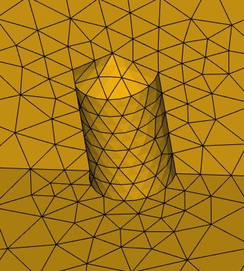
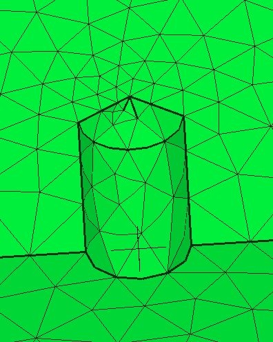
The next image shows the hole mesh. Note the two short heavy surface lines from the tip of the cone.
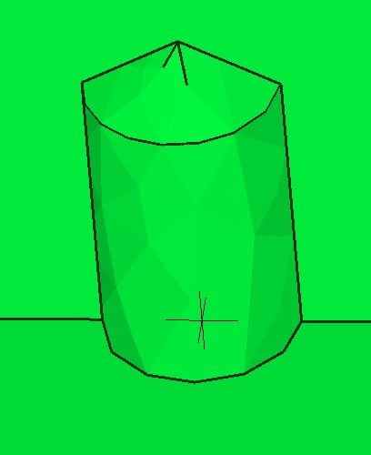
If "Show model edges" is turned off then these lines disappear. Alternately, if "Show element edges" is turned off then these lines remain (next image).
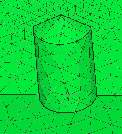
If the mesh parameter "Min number of elements per edge" is increased from 1 to 5 then the hole elements become smaller but the extraneous surface lines remain, just shorter.
If the model is rotated to a new position then the extraneous surface lines remain. From all of the above it appears that these lines aren't just display artifacts but are actual surface lines. However, they don't actually define a surface.
Note - If the step file is opened in RhinoCAD surface modeler, it doesn't show these extraneous surface lines. In fact, Rhino's error checking shows that this model should be OK - i.e., there are no naked edges.
So are these extraneous surface lines real or not? What causes them?
FreeCAD model - Cyl_100_10a.FCStd (attached as Cyl_100_10a.7z compressed file)
FreeCAD step file - Cyl_100_10a_100-Body.step
Mecway model - Cyl_100_10a.liml
Mecway 27
FreeCAD 1.0.0
Windows 10
Thanks,
Don C.
Using the FreeCAD Netgen mesher with the max element size = 10 mm but other defaults, the hole has a nice, uniform mesh.
The FreeCAD unmeshed model was then exported as a step file. Note that the first item ("Write out curves in parametric space") is not checked here. (This is normally checked by default but leads to extra Mecway nodes at the cone point.)
This step file was then imported into Mecway. The following mesh settings were used for this topic (not necessarily optimum). The intent was to later manually refine the hole walls and cone (and other details not shown in this model) while allowing the overall mesh to remain relatively coarse.
The next image shows the hole mesh. Note the two short heavy surface lines from the tip of the cone.
If "Show model edges" is turned off then these lines disappear. Alternately, if "Show element edges" is turned off then these lines remain (next image).
If the mesh parameter "Min number of elements per edge" is increased from 1 to 5 then the hole elements become smaller but the extraneous surface lines remain, just shorter.
If the model is rotated to a new position then the extraneous surface lines remain. From all of the above it appears that these lines aren't just display artifacts but are actual surface lines. However, they don't actually define a surface.
Note - If the step file is opened in RhinoCAD surface modeler, it doesn't show these extraneous surface lines. In fact, Rhino's error checking shows that this model should be OK - i.e., there are no naked edges.
So are these extraneous surface lines real or not? What causes them?
FreeCAD model - Cyl_100_10a.FCStd (attached as Cyl_100_10a.7z compressed file)
FreeCAD step file - Cyl_100_10a_100-Body.step
Mecway model - Cyl_100_10a.liml
Mecway 27
FreeCAD 1.0.0
Windows 10
Thanks,
Don C.
Howdy, Stranger!
It looks like you're new here. If you want to get involved, click one of these buttons!
Comments
Also, during generation of the surface mesh the scrolling text output says, "Singular Matrix - retry Surface 3". It then proceeds normally. (I suspect that surface 3 is the cone. Is there a way to check this?)
This doesn't occur if the hole is eliminated (see attached model).
To be honest, I never pay attention to the output of Netgen, nor understand it. It might just be saying that it found a special case which it handled correctly (mesh appears to be fine), or it might be something that went wrong.