Stuck?  support@mecway.com
support@mecway.com
Mecway
FEA
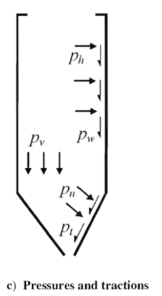
EN 1991-4 Actions on structures – Silos. Pressures on conical hopper

Hi,
I’m unable to apply my custom loads to a conical hopper using Traction (Pn and Pt according to picture).
I checked the formulas in other conditions, and they respond properly.
- Applied to the shell works fine. Symmetric result and forces are in balanc.
- Looking the result of the formula with a temperature field works fine (No undefined values or directions)
- Arrows looks good and pointing in the right directions.
When I try to apply it to the cone it fails.
Any idea what could be wrong?
https://we.tl/t-vaaqXMXdkt
Regards
Howdy, Stranger!
It looks like you're new here. If you want to get involved, click one of these buttons!
Comments
"On a shell element, the face is offset from the midsurface by half the element thickness so a traction applied to the face generates moments at the nodes as well as forces.
If you don’t want these moments, apply it to the elements instead of the faces. Then it acts on the midsurface. You should always do this for curved shells with the CCX solver because those moments usually include a normal component which isn’t allowed by CCX."
I have try to apply the traction to the elements and it works.
Hi had a little experience with silos and I encountered problems with leg joints, wind and local buckling (EN1991-EN1998 loads for seismic actions). Less problem with discharge loads, but could depend from type of bulk material.
If you are working on a complete project let me know
Regards
This model came up in a different Forum. I found it a good opportunity to try it and see which could be the drawbacks.
I have experience with Liquid and Gas storage, but powder /solids storage are a completely different world although they may look similar from the outside.
I have finished my Excel file to compute the different product loads, and I have applied them one by one and separately to the model.
When combining them one must be careful applying all of them in a Global coordinate system. Not a big deal but certainly larger expressions for unsymmetric loads patterns.
Pressures (DLOAD/DSLOAD) are transformed to *CLOADS which are affected by Transform cards around.
As a quick number pwf = μ phf. Friction coefficient depends on the Silo wall surface and Product. Values could be found in EN 1991-4 Table E.1.( μ arround .22 - .77)
That means vertical traction can be as much as a 77% of Normal pressure. That introduces a new compressive Buckling mechanism not present in Pressure vessels or Tanks under Hydrostatic pressure.
Note the code says :” The stiffness of the particulate solid should not be assumed to provide additional stability to the silo wall or to modify the loads defined within this standard”
This new to me buckling mode due to product friction on the walls seems real.
By the number of loads involved, asymmetries and extremely large D/t ratios , I anticipate solving the silo as a whole FEA project very complex.
Probably it’s more suitable to solve specific details like transition and supporting area.