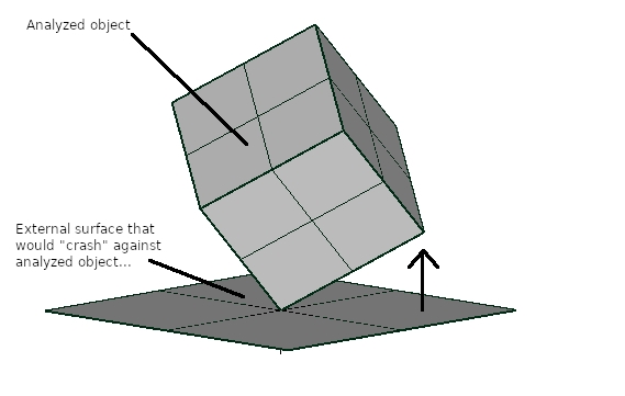
Is there a function to represent a flat surface pushed against the mesh to be analyzed?
When analyzing an object, is there a mesh / function that would represent a flat surface that is being pushed against the analyzed object? For example, when using a frictionless constrain, the program will assure that all the nodes selected with a given surface will not move normal to the plane formed by those nodes (as if an invisible external surface existed there, that would prevent the surface from moving normal to it). Similarly, if I were to press a round surface against a flat one, while analyzing the round surface compressive stresses, is there a function that could use a set of selected nodes and move them in a direction that would represent a flat surface? (like in the attached image)


Howdy, Stranger!
It looks like you're new here. If you want to get involved, click one of these buttons!

Comments
I can try to simulate the problem with a large mesh, by specifying how much each affected node will be displaced (in a simple 2D geometry and using horizontal or vertical "flat" surface, it is somewhat easy, but if it is relatively simple to do, but in 3D with a plane other than those two, it is not so easy...)
In this case, I measured the height of the node pairs on each side of the center (fixed) node, so I knew how much they would have to move downward. I am also using a specific displacement overall, so I would have to find the reaction forces to see what the actual applied load is. Then, I had to solve the problem 3 times to see if the next pair of nodes are below y=0 (the "floor"). If so, then I applied their displacement so they would "stop" at the floor...
This problem takes 5 iterations, and yet it is a trial-and-error since there is no easy way to establish any correlation between the overall circle downward displacement and the extend of nodes that will reach the flat floor...
If you really don't want to mesh the flat surface, you might use a gap element on each node. That allows you to specify the distance before the contact closes. But there isn't a formula input so you'd have to calculate their gap sizes externally. But I don't think there's any need to and you should just mesh the surface (as a solid element, not shell).
May I ask you which load would cause that displacement pattern?
Are those strict displacement imposed for some theoretical validation?
Thank you for your feedback. I did some research on the gap element you mentioned (I don't know if MecWay has something like Nastran's gap elements), and then I search for the same on MecWay manual, and found that using non-linear Static analysis (CCX solver), there is an actual "contact" function (similar to ANSYS) and it worked. Unfortunately it does not exists for 2D Static simulations...
The example I show above does not require any particular load or displacement; it is just an example that shows many situations one encounters when designing products with materials that can deform significantly under load (e.g., polymers). Many times contacts change due to loads, and for that purpose, some FEA software like ANSYS, for example, uses "contacts" to keep track of those elements. I was just wondering if MecWay has a simpler, one-component analysis tool that could simulate a simplified "wall" that comes in contact with the object. Or perhaps, an equation function that one could use to do so instead of having to resort to a non-linear contact method. As you can see in the 2D object above, I used very large quadratic elements and I don't mind finding distances and applying the appropriate displacements to specific nodes; but if I had to refine the mesh to very tiny elements, that task becomes very time-consuming and open to mistakes, not to mention the number of solution iterations also goes up significantly.