Hint about .step file preparation

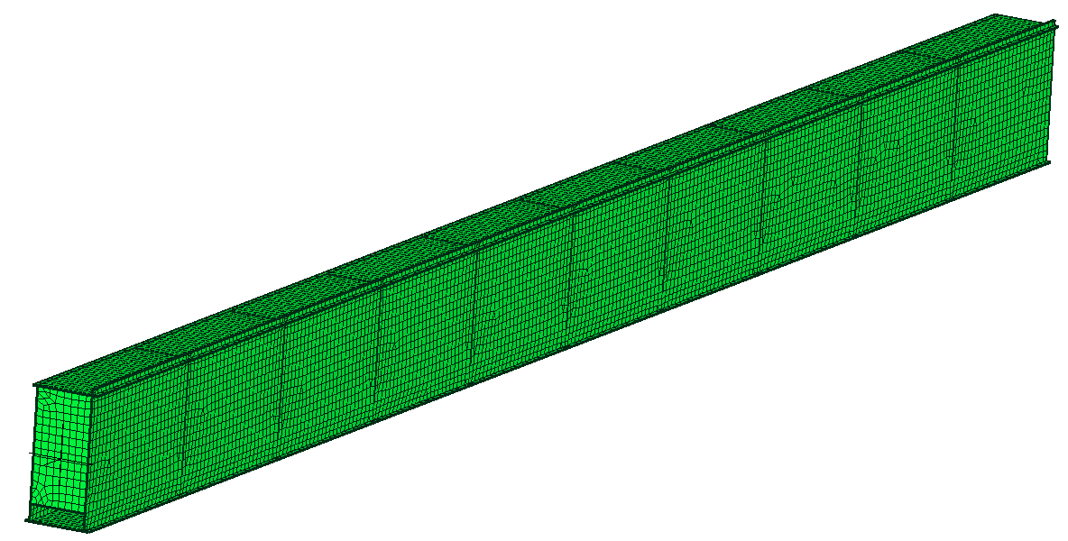
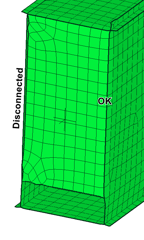
I often work with welded box section and so I prepared a CAD parametric model to build the complete girder (shell). The problem is that all the times I must import the step file into FeeCAD and apply fuse command because the diaphragms are always disconnected on one edge (see picture). All other surfaces (webs, flanges and rail) are meshed correctly
I use SW to build the CAD model
Comments

  • Have you tried with Gmsh? It tend to be better at this than Netgen.
  • It's worst...all surfaces are separated.

  • edited July 2024
    Are you sure that the surfaces are perfectly touching in CAD? Were all generated by the same kind of operation? Some times the extend surface operation gives some degenerated edge that doesn´t allow a connected mesh. If I remember well there is a tool to see the unsewed edges in SW, and also another to sew them with a tolerance value.

    I have made in the past some consultancy work on similar models and I remember that the CAD model were not perfect, lot of very small imperfections and I had to fight a lot to make it mashable with coincident nodes in Salome. Maybe you can just use "TIE" and don´t waste to much time looking for that imperfections.

    Feel free to upload the models (native and step), maybe we could see if we found the gap.
  • Have u tried selecting the whole model once it is meshed and and then "merge near by nodes" and slowly increase the tolerance and see if it connects the nodes at the surface edges?? I
  • I tried! Sometimes it runs because the nodes are very closed (2/3 mm tolerance). Other times it degenerates the mesh
  • edited July 2024
    Another test that you may do is extend the surfaces in SW (away from the target), and then trim the excedent with the other, and finish with a sew command in SW before importing in Mecway.
Sign In or Register to comment.

Howdy, Stranger!

It looks like you're new here. If you want to get involved, click one of these buttons!