Plastic deformation
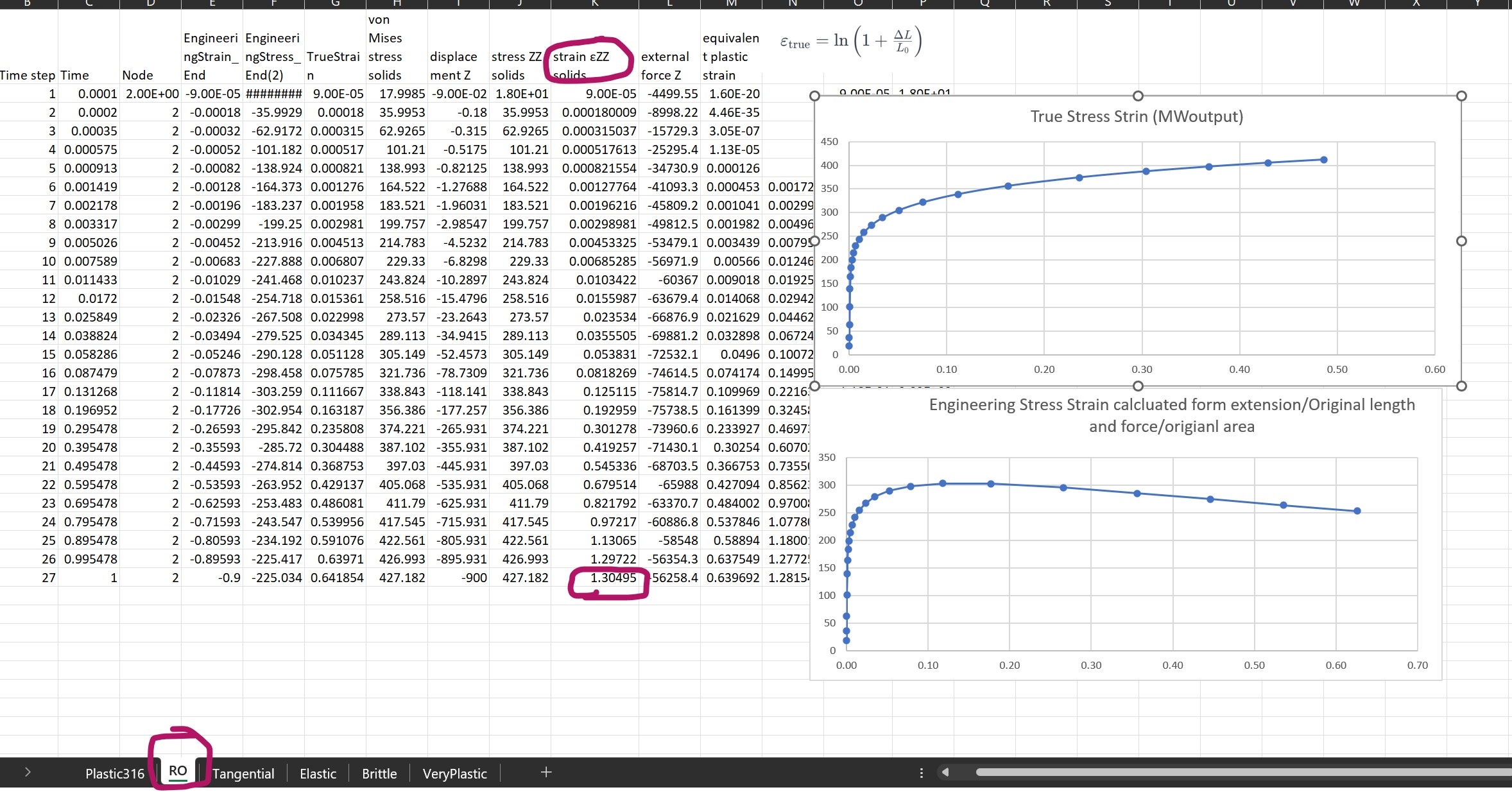
I was keen to understand some of the different methods of looking at plastic deformation. Having made the mistake of using complex structures to examine this before, I started with a (perhaps overly simple?) 1m cube. I restrained one end so that it was free to shrink in the off axis directions and pulled the opposite face 900mm. I then made up some variables to try and evaluate Engineering Stress and Strain and a form of True Stain using ln(1+deltaL/Lorginal).
The MW file is attached -the list of material properties I used are in the "unused material" list. I ran thru a number of plastic material options and placed the results on different sheets of the attached spreadsheet.

Most of what I see in this study is as I expected however it has generated a few questions I would really like to know if anyone can hep me with.
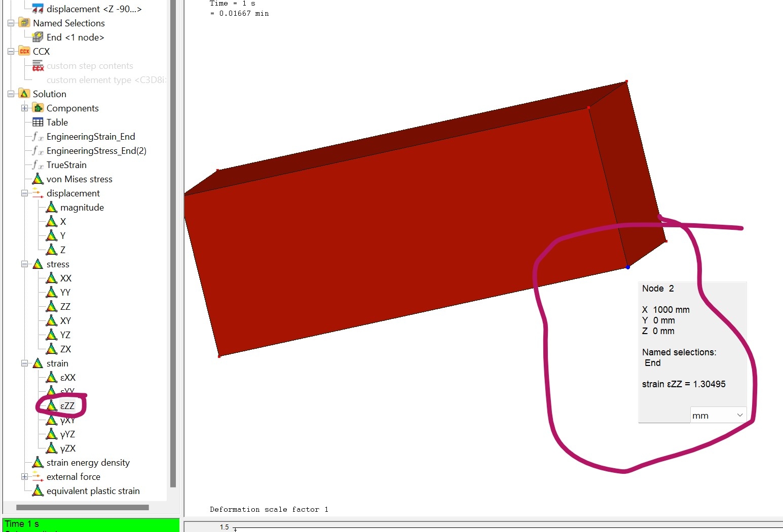
1/ what "strain" is Mecway generating in the ZZ direction -i see something like 1.30495 (same for principle strain in 1 axis) when my block has been stretched 900mm -I don't see where this strain comes form. Coincidently, it is very close to the sum of my generated true strain variable and the plastic strain generated by MC.

2/just to be complete I ran one analysis with a complete elastic material and as initially surprised to see a non linear relationship between stress and strain in my calculated engineering stress/strain - is this something to do with the change of section area or just an indication I have generated my Engineering Stress/Strain numbers incorectly.
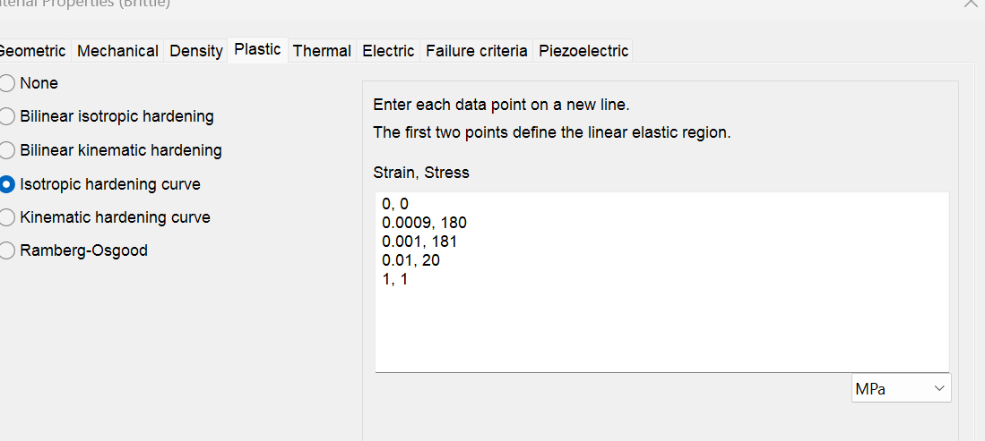
3/ The main reason this study was to see if I could generate a "plastic" material property that would mimic the Abaqus "element deletion" model so I could look into failure mechanisms. I looked at one material I called "brittle"

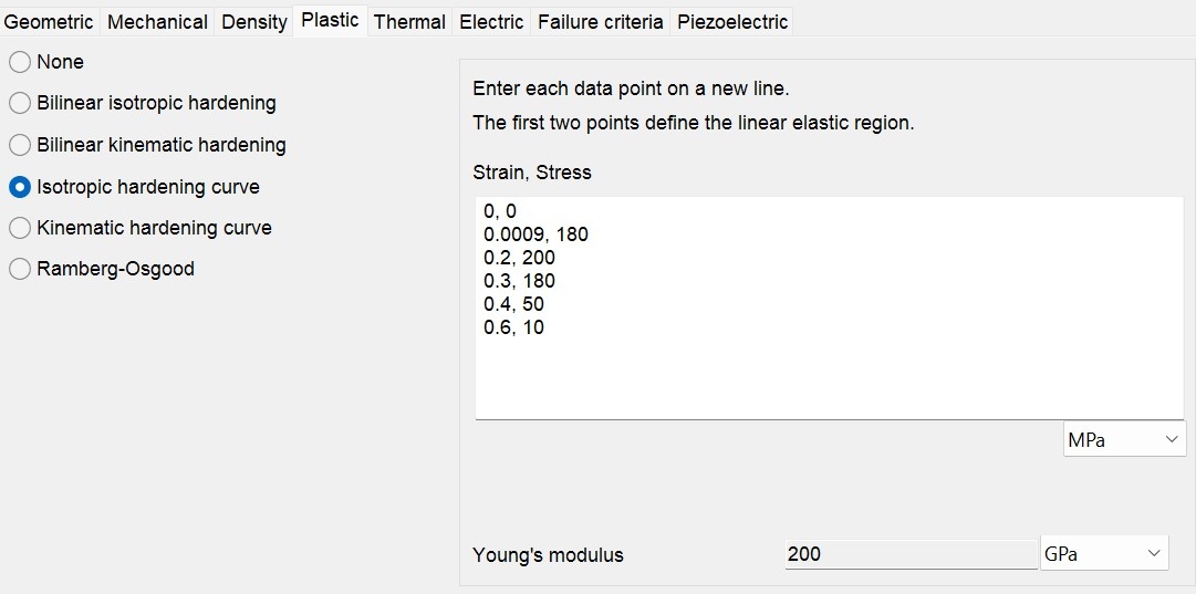
and another I called very plastic

These 2 tests appeared to behave as I wanted in a single element but I have yet to see how they behave in a more complex "real" structure. My question is has anyone got some guide lines on how to produce material properties that will "degenerate" in a somewhat controlled manor that will allow non linear modelling to study failure mechanisms of real structures. My goal is not so much to get accurate numbers but more to get a feel for failure mechanisms.
The MW file is attached -the list of material properties I used are in the "unused material" list. I ran thru a number of plastic material options and placed the results on different sheets of the attached spreadsheet.

Most of what I see in this study is as I expected however it has generated a few questions I would really like to know if anyone can hep me with.
1/ what "strain" is Mecway generating in the ZZ direction -i see something like 1.30495 (same for principle strain in 1 axis) when my block has been stretched 900mm -I don't see where this strain comes form. Coincidently, it is very close to the sum of my generated true strain variable and the plastic strain generated by MC.

2/just to be complete I ran one analysis with a complete elastic material and as initially surprised to see a non linear relationship between stress and strain in my calculated engineering stress/strain - is this something to do with the change of section area or just an indication I have generated my Engineering Stress/Strain numbers incorectly.
3/ The main reason this study was to see if I could generate a "plastic" material property that would mimic the Abaqus "element deletion" model so I could look into failure mechanisms. I looked at one material I called "brittle"

and another I called very plastic

These 2 tests appeared to behave as I wanted in a single element but I have yet to see how they behave in a more complex "real" structure. My question is has anyone got some guide lines on how to produce material properties that will "degenerate" in a somewhat controlled manor that will allow non linear modelling to study failure mechanisms of real structures. My goal is not so much to get accurate numbers but more to get a feel for failure mechanisms.
Howdy, Stranger!
It looks like you're new here. If you want to get involved, click one of these buttons!

Comments
-First let me tell you I like to express imposed displacements as it’s equivalent Stretch.
Stretch do not depend on the Strain framework, and it is in my opinion, the perfect link between all later strain forms.
-Your Stretch is not 900mm. Your Stretch (commonly refer as Lambda in many books) is 1.9 [ ] and it doesn’t have dimensions.
-Use the right name for each strain and be sure you know to which strain are others referring when talking to you, reading papers, books, …
-I recommend you go very deep into this subject until you clear all your doubts. This is part of FEA foundations.
-Rebuild your cube with the right definition of Stretch (better if you impose a positive z to start) and write all your formulas for each Strain in terms of Stretch. Then compare with the expected value. I'm sure you will clear many doubts and some others will arise.
I have also noticed that you should also take a look at your graphs. They don't seem consistent with your results. They reflect the importance of distinguishing correctly not only the stresses but the Strain you are talking about.
Enginieering Stress & Enginieering Strain Curve.
Enginieering Stress @ ( 0.9 Enginieering Strain) = 225 MPa
True Stress & True Strain Curve.
True Stress @ ( 0.64 True Strain) = 427 MPa
My focus was more to see how the different types of plastic models work and compare against each other. Also to see if I could get help on material definition that work let me look at failure mechanism of structure post yield, I'm guessing some of my post yield convergence issues are caused by my plastic material definitions. So I'm still keen to hear if anyone has ideas/pointers that could help me there.
If you want to use them to plot a Stress Strain Curve (whatever True or Engineering), need to be converted first.
Regarding Plasticity:
ccx manual says:
1-All CalculiX input (e.g. distributed loading) and output is in terms of true stress.
2- The hardening curve should yield the von Mises (true stress) versus the equivalent plastic logarithmic strain (cf. deformation plasticity for its definition).
That means , if you have available an Engineering Stress vs Engineering Strain from laboratory , you need to convert them to Logarithmic (True) Stress and Logarithmic (True) Strain.
Mecway request first two points of the Curve to define the Elastic part of the behavior up to the Yield Point, and from there (From the Yield Point) you introduce the hardening area where the plastic Strain starts. All the input values are in terms of Logarithmic (True) Stress and Logarithmic (True) Strain.
For Example, your Aisi 316 which is the one I can recognize:
0, 0
0.0008221, 170000000
..
.
.
0.9988, 510000000
510MPa is the Ultimate strength?. That value is an Engineering Stress not a Logarithmic (True) Stress. You need to convert it. That stress is not reached at a Logarithmic (True) plastic Strain of 99.8% but way before.
Here you have some data from experimental test (Enginieering values) for AISI 316 @ Room temperature for reference. Note how they correctly distinguish between Enginieering and True Strain at the abscissa.
https://www.sciencedirect.com/science/article/pii/S1738573320304587