Stuck?  support@mecway.com
support@mecway.com
Mecway
FEA
Stress linearization for weld analysis

Post from @kuhl
Thanks @Victor, another valuable addition!
A couple of weeks ago I promised to dig out a an illustration showcasing the stress components that I would be interested in in order to use the stressliarization tool in Mecway for weld analysis:
Or, alternatively illustrated:
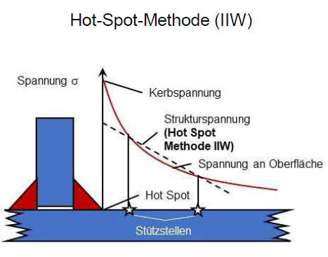
The stress linearization could be used to evaluate the hot spot stress components in singularities, eg at the toe of a weld, where the stress cannot be taken directly because it does not converge. Either by linearization along the surface according to IIW (International Institute of Welding)
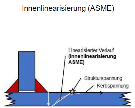
or by linearization through the thickness according to ASME
I hope that helps as an explanation.
A couple of weeks ago I promised to dig out a an illustration showcasing the stress components that I would be interested in in order to use the stressliarization tool in Mecway for weld analysis:
Or, alternatively illustrated:
The stress linearization could be used to evaluate the hot spot stress components in singularities, eg at the toe of a weld, where the stress cannot be taken directly because it does not converge. Either by linearization along the surface according to IIW (International Institute of Welding)
or by linearization through the thickness according to ASME
I hope that helps as an explanation.
Howdy, Stranger!
It looks like you're new here. If you want to get involved, click one of these buttons!
Comments
- Find a linear function for stress along the SCL line.
- Stress is in a user-defined orientation, which can be the element coordinate system.
- Only the 6 stress components are needed, not von Mises, principal stress, etc.
- Two linearization methods:
-- Interpolate and extrapolate from two user-specified points (stutzstellen) on the SCL that are additional to the two end points of the SCL. (Hot-Spot-Methode IIW)
-- Some other method (ASME) using a single user-specified point. How does that work?
- Both methods only use the stress at the stutzstellens, and ignore stress elsewhere along the line.
That should be fairly easy to add once I'm clear on the requirements.
After that must be made an extrapolation (linear or quadratic) to the hot spot.
IIW prescribes some different mesh dimension. Maybe attached picture is more clear
first, I found this article explaining the differnt methods for evaluation hot spot stress. It is in german originally, but google translator does an ok job, exept that it confuses stress with voltage (same word in german).
https://www-einbock--akademie-de.translate.goog/die-wichtigsten-methoden-zur-berechnung-von-schweissnaehten-nach-dem-strukturspannungskonzept/?_x_tr_sl=auto&_x_tr_tl=de&_x_tr_hl=de&_x_tr_pto=wapp
Concerning IWW
There are quite a few variables that define what has to be done. If implementation in Mecway is too complex due to too many choices, it would be a trade-off solution to just output the required stress component along the SCL and do the linearization afterwords in excel or similar. For that it would be handy to have mm as unit for the x-Axis of the stress plot to easily extract the stress from the plot at the required location.
Concerning Internal Linearization (ASME)
The stress is linearized through the entire sheet thickness. The stress inside the plate below the weld transition is divided into membrane, bending and notch portion. Membrane and bending stress result in the structural stress.
So as i understand it, this method is very close to what is already there in mecway. Just that at the moment it is not possible to choose the required stress components.
Here a screenshot as reference:
It's an extra option that shows the 6 components in the SCL coordinate system, interpolated along the SCL, and not linearized. This requires you to specify one other axis (I chose M) of the SCL coordinate system.
It would also show the 3 axes (Tangential, Meridional, Hoop) on the model to verify their orientation.
It would be convinient to have mm on the x-axis and in the table in addition to the points 1 to 99 like in the screenshot from my last post .
Not the linearized components (membrane/etc.) because ASME pressure vessels uses the components but not the linearized components. If I can get a clearer picture of what these other codes require, I'll add linearized components too. For example, some of the 6 are not needed?
Another concern I have is the naming of the axes. T,M,H may be specific to pressure vessels and/or ASME and confusing for anything else.
Yes, mm distances in table.
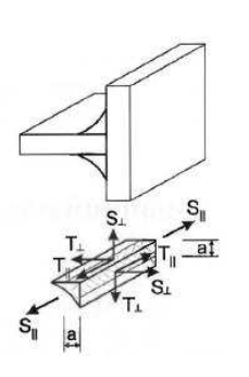
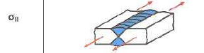
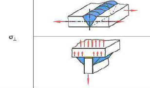
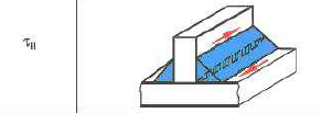
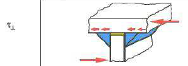
the components that are needed for weld assessment accornding to FKM "Analytical Strength Assessment" are:
Stress normal to weld
Stress parallel to weld
shear stress normal to weld
shear stess parallel to weld
as shown in this image:
So depending on the orientation of the SCL (trough thickness [ASME] or along surface [IIW]) the stress component in correlation with the local SCL coordinate system would be different depending on the use case?
Maybe it is the least confusing to just call the axis 1,2 3 or a, b, c so it does not trigger a realtion to a stress component...
accornding to FKM "Analytical Strength Assessment" you can get the hot spot stress by using the ASME linearization method in thickness direction (hot spot stress = membrane + bending of the respective component) or by using IWII method.
For ASME I think it would be neccessary to do the linerization (membrane, bending) within mecway. For IIW I think it would be best do do the linearization externally (excel) using the methods I postet on june 16th because it would be too complicated within mecway with all the different parameters?!
Maybe the components to show in the diagram could be toggled on / off by using checkbox, so the user can choose what he / she wants to compare without getting overloaded...
The trouble with them all being option is there are a lot of options (44). Maybe it can just be a giant table or list of checkboxes for maximum freedom:
I'm a bit confused with the 3 axes (Tangential, Meridional, Hoop). Isn't tangential the same direction as hoop? For nomenclature's sake with pressure vessels I'm equating tangential=circumferential=hoop, meridional=longitudinal=axial, radial=normal?. No? Sorry, but I'm wishing for an axes graphic.
@kuhl: As for the IIW Hot-Spot method, I think a 2-3 point node pick into a python script is handily done on a stress vector (maybe on a Solution/formula), but are you more wanting a graphic plot of the stress-line for documentation purposes?
I'll probably name them 1,2,3 or x,y,z or even ASME's (3rd naming convention!) X_L, Y_L, ... which is nice but leads to subscripts on subscripts.
With the interpolated plot/table it would be easy just to exteact the values from that.
But maybe I am missing something here ...?
And yes, clear documentation is always a very valuable addon.
I have done some test on the new tool features based on a given reference (*) and deviation has end up below 0.17%. (Even better than the Ansys reference)
Things found on the test:
1-I can't change the SCL direction. Even switching the points.
2-If SCL-y axis is requested to be aligned with a Global Axis that it is aligned with the SCL there is no output.
3-Linearization tool works with Shells in a 3D space but not when switching to 2D.
(*) https://fatigue.pro/2023/02/freecad-fem-results-in-fatlab/#LinearizedStress
1 - Direction is away from the origin. Not sure what the reasoning behind this originally was but a more obvious first point to last point must have had some problem.
2 - The SCL direction itself is its x axis, so y can't be parallel to it.
3 - It's not really meant for shell elements so it's just an accident that it works on CCX expanded shells.