Mecway Formula
Hello Victor!
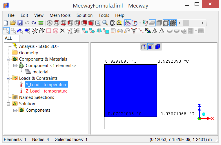
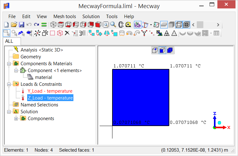
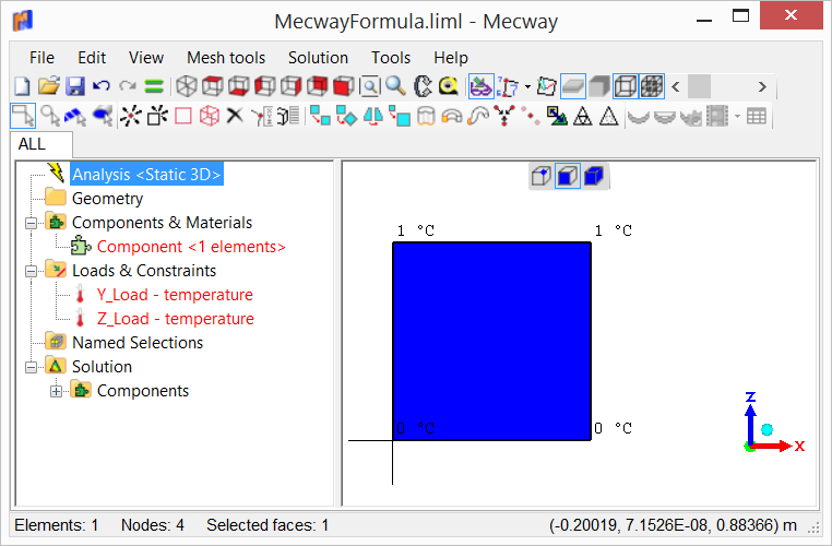
The formulas in Mac Way is a very powerful feature. But I think that I did not understand how to use them. I created an inclined plate as shown in the attached file. The loads should be as a function of y and/or z coordinates. I created temperature loads to check loads values as suggested in this forum. But the values I found are complete different from what I expected. All points of my structure has y coordinates equals to z coordinates. If I change from y to z the values change. And more if I delete the material in tree, all values became as I expected! I found this behavior very stranger!
Would you please help me?
Thank you!


Howdy, Stranger!
It looks like you're new here. If you want to get involved, click one of these buttons!

Comments
If you apply the formula to the nodes the value will be the same as the node coordinates.
As you are applying the temperature to the face of a shell, the value shown is the coordinate of the corresponding expanded surface (it will change depending on the shell thickness.
Thank you for you reply!
I think it is a very stranger behavior! My real load is a pressure that varies with z. If I use formula, the applied pressure varies with the thickness of the plate(!!!!). For me, it really don't make sense! I created a new Macway model (attached) without gravity load. When I change the shell thickness, the reaction forces change! So, I think that I can not use formulas to describe loads with accuracy.
Any help will be welcome.
Thank you!
The shell is an idealization, the midplane of something with thickness.
If you apply the formula to the shell (midplane) , MECWAY is translating the value to the surface.
In the extreme case of your wall completely horizontal and under hydrostatic pressure, once expanded , each side will have different hight (pressure). One face goes up and the other down.
If you want the same value no-matter the thickness, the formula P(z)=z is not well posted.
According to what is happening, there should appear a temperature or pressure gradient inside the element once solved. Is not trivial. Very interesting what you found.
EDIT: If you want the value to coincde with the Z of the midplane you can offset the wall half the thickness.
Thank you for your suggestion! Your suggestion is really a very clever solution for shells with constant thickness. I tested and it works fine. I will use it for sure. But the structure that I'm analyzing at this time is an channel of a spillway of a dam of a hydroelectric power plant with retaining walls of varying height and thickness as shown in image below. As the retaining wall thickness also varies, it became almost impossible for me to define a formula to describe the ground pressure on the wall. It would be f(x,y,z). A feature that I would love in Mecway would be to be able to define the average thickness of the elements in the shell model using formulas.
If someone has an suggestion to solve my problem, I will appreciate.
Thank you!
If you really want pressure to use midplane coordinates, you can use traction instead which can be applied to shell elements instead of faces and it uses the midplane coordinates. The main disadvantage is that you have to define the normal direction yourself but it should be easy for flat walls like this.
I agree formulas for shell thickness as well as offset would be helpful but aren't there yet.
@Victor, thanks for your answer. I'm new to Mecway and hadn't considered the option to use traction load. The shell offset feature also helps a lot. Congratulations on your work! Mecway surprises me every day with the features and facilities it offers. I hope formula for shell thickness come as soon as possible.
Thank you!