Spring connection
Hi,
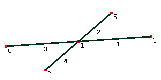
I want to create a spring connection between two metal beams that are connected by a bolt. The first beam (elements 1 and 3) crosses the second beam (elements 2 and 4) at the position of the superimposed nodes 1 and 4.
I tried to create a line2 spring element between nodes 1 and 4, but to do that I need to create a small offset between the nodes 1 and 4 and the line2 spring element created is then directionnal, and I'd like the spring not to be directionnal (same stiffness in every direction).
I could perhaps create 3 constraint equations (1 for each translational dof) between nodes 1 and 4. But then it is not a spring (infinite rigidity of the connection). Furthermore, I will need to create hundreds of such connections. I do not create them "by hand" but is there a limitation on the number of constraint equations ?). So I have the following questions
- is there a better alternative to implement spring elements ?
- is there a limitation on the number of constraint equations ?
- does constraint equations work for Static 3D and Modal vibration 3D. It seems to work on a small example (4 elements), but 3D is not mentionned in the manual, is there some limitations ?

Howdy, Stranger!
It looks like you're new here. If you want to get involved, click one of these buttons!

Comments
I don't know of any limit on the number of equations, but the GUI will become slow if there are too many items there maybe 1000s or so.
Yes, constraint equations work for 3D. When it's not mentioned in those lists in the manual, it means all the options under that name.
An ugly way might be to build a nearly-rigid structure around the joint to support each beam on ordinary axial springs. You'd have to give the nodes or beams of this structure some small mass to ensure it can solve. Here's an example of just a spring in the common normal direction. I've separated the two beams for clarity.
Or, more elegantly, you could avoid the extra structure by using a constraint equation to couple the free end of a spring to the other beam.
I am not familiar with CCX command lines. Could you give me a minimal working example in liml format to get me started ?
I've found this topic but I'm not sure what to do with it : https://mecway.com/forum/discussion/171/creation-of-ccx-spring
What's going on in the CCX branch of the outline tree is:
- custom element type causes all the line2 elements its applied to to be SPRING2 elements.
- custom model definition defines the direction (1,1 for X, 2,2 for Y, 3,3 for Z) and spring constant.
For multiple springs in the same direction, just make them as line2 elements in the mesh and include them all in the same named selection (here, "z_spring_elements" for Z).I tried your solution with CCX SPRING2 elements and it works well. However I cannot postprocess the way I am used to with Mecway internal solver. Namely I like to be able to see axial forces and stresses (not possible with option SECTION FORCES of CCX), and to get export values (using tables) by elements (and not by node) for my own postprocessing (I could not find a way to do it with CCX solver).
Here is what I did to keep using Mecway internal solver. I deleted the intersection node (10 below on the left figure) and created (on the right figure) :
- 4 nodes (2 4 3 8)
- 4 bar elements (2-4 4-3 3-8 8-2) of spring type
- 2 bar elements (2-3 and 4-8) of same type as the bars on the left figure, without any intersection node
This is roughly equivalent to the non directionnal spring I was looking for (and I can control the rotational spring by changing the position of created nodes). It would be great if Mecway add an element type similar to SPRING2 of CCX. Could it be a future new feature ?I still have one more question : is it possible to see graphically the axial forces in bar elements of spring type ?
This might be a lucky accident but if you assign a section shape to the spring material in the Geometric tab with the internal solver, it appears as a solid beam in the solution, colored according to the variables like axial force. The section properties are ignored by the solver when it's a spring type so just choose anything that looks reasonable.