Stuck?  support@mecway.com
support@mecway.com
Mecway
FEA
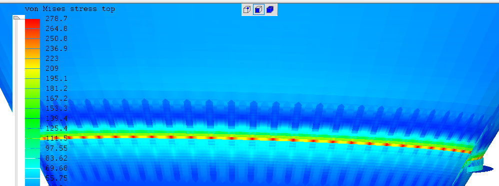
Uneven stress levels around a cone

See the attached image and file. Does anyone know why the stress around the cylinder varies. I expected a near constant value. How do i get a more constant peak stress ring?
Howdy, Stranger!
It looks like you're new here. If you want to get involved, click one of these buttons!
Comments
There are sometimes also cases where shells have these kinds of alternating stresses and you may have to ignore those localized regions or average them.
Is there anyway to force smooth to keep the Y co-ordinate and smooth the X and Z
Also note the local axes for RSA components. How Do i get these to be correct i.e. either U or V radial.
To set the element axes so U is the radial direction, make another element orientation in Loads & Constraints with these values:
X: x
Y: 0
Z: z
Then when i find the max stress point and refine it the value just increases every time i refine it further. What am i doing wrong?, see attached
Also see attached screen capture showing max a
nd min. How ca the save point be both?
Find Max/min only looks within the current selection, so ensure nothing is selected before using it. This feature is useful to exclude uninteresting stress concentrations.
I’m getting soft Von Misses result.
Check the deformed view of your result to see if it has sense. If it blows to hell or goes out of your axis center your BC are probably wrong and Stresses are nonsense.
It is not mandatory but preferably build a conformal mesh between shell and stiffener. The easiest way is to draw a 2D section and revolve it.
If your stiffener is not a supporting element I would suggest you to re-orient it. Think it as a beam. The reinforcing material is recommended to be as far to the vessel shell as possible to increase second moment of inertia.
Keep also in mind that in order to be effective the stiffened area should be at a “small” distance from the weakest areas (cone transition).
But in reality, there are probably localized high stresses you don't care about and don't need to model accurately because they won't lead to failure, or that you can calculate some other way. Those decisions about what to ignore are more engineering than FEA.
I have tried created a solid model, see attached. And think it is at the yield point, when permanent deformation would occur, although the deflection is much lower than 5mm.
von Mises stress exceeding yield at any location will mean permanent deformation as long as the material follows the von Mises yield criterion. But maybe your client has a more practical definition of "permanent deformation" that excludes some unimportant one?
Now that it's solids, you really need to use quadratic elements (hex20, wedge15, etc). Linear solid elements in Mecway are poor at bending and some components of their stress are constant through their thickness which means you would need many elements in the thickness direction to capture differences between one side of the plate and the other. So quadratic elements are much more efficient in terms of mesh density.
The maximum stress in this model is very close to or at the connection between the angle support and the cone so you definitely need to refine the mesh in that region until it doesn't change, but there are also stress singularities there (what I earlier called infinite stress concentrations), so you have to ignore those and look at the values some fixed (not reducing with mesh refinement) distance away from them.
The clients doesn't have any other definition of the permanent deformation. He just needs to give a value to his buyer.
If it's from a flat STEP or IGES file, that's a bit easier. Right click a node and choose New local refinement which makes a sphere of refined elements next time you generate the mesh.
Regardless of how the mesh was made, you can select the elements to refine and use Mesh tools -> Refine x2 but it makes some not very well shaped transition elements and you can't turn it off later.
If you still have the persistence, you can switch to nonlinear analysis and define a plastic material so you can see if the inevitable yielding that occurs in this pathological case of a perfectly sharp corner is self limiting or if it leads to large scale deformation.
Don’t underestimate what you got. You problem is not trivial at all.
I dare you to find a code which analytically solves the transition between a skirt and a cone with the supporting line "in the cone" itself.
It is not by chance that 99.99 % of the supports for vessels are located in the cylindrical area or at least, transition area.
Google some images of “silo skirt support” and check how many of them have the skirt resting in the middle of the cone as yours. Your skirt is very special.
Also, the cone has a half apex angle of 30º which is the limit in where most codes feel comfortable.
The FEM is giving you good information from my point of view . You have a dangerous closed ring of peaks stress through all the thickness on a thin shell that in my opinion will hardly be able to redistribute stresses to other areas allowing a safe path (maybe with a belt).
Do not feel frustrated and don’t be discourage, peak stresses are “the daily bread” in FEM.
I think i'll leave the mesh as it without further refinement and reduce the pressure load. since the deflection is no where near the 5mm limit I'll also run it with increasing pressure until i get 5mm deflection then advise him on the theoretic yield pressure limit and theoretic deflection limit pressure.
I'll try remeshing surface with 3 element through the thickness and revolve again
https://mecway.com/forum/discussion/362/mesh-convergence/p1
Here's the text link, in case that one does not work:
https://mecway.com/forum/discussion/362/mesh-convergence/p1
I tried Non linear static and get some errors, I.e. bonded contact and member orientation
What do i need to change these to to get it to analyse?
*INFO reading *STEP: nonlinear geometric
effects are turned on
*WARNING reading *STATIC: a nonlinear analysis is requested
but no time increment nor step is specified
the defaults (1,1) are used
STEP 1
Static analysis was selected
Nonlinear material laws are taken into account
Newton-Raphson iterative procedure is active
Nonlinear geometric effects are taken into account
*INFO in gentiedmpc:
failed nodes (if any) are stored in file
WarnNodeMissTiedContact.nam
This file can be loaded into
an active cgx-session by typing
read WarnNodeMissTiedContact.nam inp
*WARNING in gentiedmpc:
DOF 3 of node 14 is not active;
no tied constraint is generated
*WARNING in gentiedmpc:
DOF 3 of node 15 is not active;
no tied constraint is generated
*WARNING in gentiedmpc:
DOF 2 of node 16 is not active;
no tied constraint is generated
*WARNING in gentiedmpc:
DOF 3 of node 16 is not active;
no tied constraint is generated
*WARNING in gentiedmpc:
DOF 3 of node 19 is not active;
no tied constraint is generated
*WARNING in gentiedmpc:
DOF 3 of node 20 is not active;
no tied constraint is generated
*WARNING in gentiedmpc:
DOF 3 of node 23 is not active;
no tied constraint is generated
*WARNING in gentiedmpc:
DOF 3 of node 24 is not active;
no tied constraint is generated
*WARNING in gentiedmpc:
DOF 3 of node 25 is not active;
no tied constraint is generated
*WARNING in gentiedmpc:
DOF 3 of node 33 is not active;
no tied constraint is generated
*WARNING in gentiedmpc:
DOF 3 of node 34 is not active;
no tied constraint is generated
*WARNING in gentiedmpc:
DOF 3 of node 35 is not active;
no tied constraint is generated
*WARNING in gentiedmpc: no tied MPC
generated for node 90087
no corresponding master face
found; tolerance: 9.4836489698703799E-005
*WARNING in gentiedmpc: no tied MPC
generated for node 90088
no corresponding master face
found; tolerance: 9.4836489698703799E-005
*WARNING in gentiedmpc: no tied MPC
generated for node 90175
no corresponding master face
found; tolerance: 9.4836489698703799E-005
*WARNING in gentiedmpc: no tied MPC
generated for node 90389
no corresponding master face
found; tolerance: 9.4836489698703799E-005
*WARNING in gentiedmpc: no tied MPC
generated for node 90390
no corresponding master face
found; tolerance: 9.4836489698703799E-005
*WARNING in gentiedmpc: no tied MPC
generated for node 90429
no corresponding master face
found; tolerance: 9.4836489698703799E-005
*WARNING in gentiedmpc: no tied MPC
generated for node 90541
master face too far away
distance: 9.5216759056826472E-005
tolerance: 9.4836489698703799E-005
*WARNING in gentiedmpc: no tied MPC
generated for node 90656
no corresponding master face
found; tolerance: 9.4836489698703799E-005
*WARNING in gentiedmpc: no tied MPC
generated for node 90658
master face too far away
distance: 1.0484692903400816E-004
tolerance: 9.4836489698703799E-005
*WARNING in gentiedmpc: no tied MPC
generated for node 90988
no corresponding master face
found; tolerance: 9.4836489698703799E-005
*WARNING in gentiedmpc: no tied MPC
generated for node 91071
no corresponding master face
found; tolerance: 9.4836489698703799E-005
*WARNING in gentiedmpc: no tied MPC
generated for node 91453
no corresponding master face
found; tolerance: 9.4836489698703799E-005
*WARNING in gentiedmpc: no tied MPC
generated for node 91459
no corresponding master face
found; tolerance: 9.4836489698703799E-005
*WARNING in gentiedmpc: no tied MPC
generated for node 91583
master face too far away
distance: 1.0454032460183171E-004
tolerance: 9.4836489698703799E-005
*WARNING in gentiedmpc: no tied MPC
generated for node 92061
master face too far away
distance: 1.0412599186349070E-004
tolerance: 9.4836489698703799E-005
*WARNING in gentiedmpc: no tied MPC
generated for node 92228
master face too far away
distance: 1.0166276223055881E-004
tolerance: 9.4836489698703799E-005
Decascading the MPC's
*INFO in cascade: linear MPCs and
nonlinear MPCs depend on each other
common node: 92290 in direction 2
*ERROR in cascade: zero coefficient on the
dependent side of an equation
dependent node: 14 direction: 1
Regards
*INFO and *WARNING messages are often normal and harmless. These ones look OK.
*ERROR is what makes it fail. This one looks like it might be the same problem as the "incompatible constraints" message that the internal solver gives on bonded contact and displacement on the same nodes. If it's solid elements, check node 14 to see if it is. If it's shell elements, the node number might not match the input model. With CCX, you may be able to avoid it more easily by selecting the Elastic option in bonded contact and entering a high stiffness value.
? main step file used is only the profile shape of the cone and angles that i have then meshed and revolved. two other step files are the stiffeners which have been surface meshed then extruded 5mm.
Victor
tried elastic instead of tied changed bolts material from circular to rectangular bar, changed rsa material to rectangular bar, changed isotropic material to plastic material with yield of 275 mpa sectant modulus of 0.5% of E, ticked quasistatic with time of 1s step of 0.5s
it takes about 60 iterations to solve, but stiffeners aren't connected and there are no stress results only deflection s and external force. whats this?
disla
files attached.
The stiffener comes away because the stiffness of the bonded contact joint is too low. I changed it to 1000 GPa/m and it stays pretty close.
I also changed the pressure load from constant to ramped by replacing "92.6" with "92.6*t". That not only makes it easier to converge, but if it fails, you can sometimes see successful solutions before the failure and get an idea of what went wrong. It now only takes 6 iterations.