Stuck?  support@mecway.com
support@mecway.com
Mecway
FEA
Workflow for importing truss geometry from CAD?

I have a handful of existing truss structures that I wish to compare, similar to this
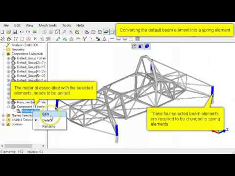
or this:
http://mecway.com/forum/discussion/423/nonlinear-3d-with-beam-elements-for-spaceframe-car-chassis
They are built using the Solidworks 3D sketcher, which I can export to STEP and open in FreeCAD. However, Mecway only imports solids from STEP files, not lines or curves.
If I want to avoid re-building each truss using the Mecway modeller, which of the formats that Mecway imports will capture this type of geometry, and how can I produce these files? The Mecway manual indicates that it can import UNV files, which is listed as an export format in FreeCAD; however FreeCAD fails to actually export a UNV file. I suspect I am missing a step.
Has anybody done anything similar, and can share their workflow?
Howdy, Stranger!
It looks like you're new here. If you want to get involved, click one of these buttons!
Comments
https://forum.solidworks.com/thread/50774
Here are some suggestions for exporting a list of point coordinates. You would be able to import that as the very simple .xyz file format in Mecway but would still have to add the elements by hand as Sergio said.
https://forum.solidworks.com/thread/21628
It sounds like if I can find a way to produce a 3D DXF using whatever tools I can get my hands on, then the wireframe geometry from that file will appear in Mecway?
in MW you can assign section element then changing the properties to truss from icon menus.
2. Mesh as surface with quad dominant, min. no elements per curve and edge =0, size grading set to aggressive (few elements).
3. This will give large elements with nodes and edges in all required line locations. Delete any extra elements if you wish to clean up but not required.
4. You can create new component and create new 2D elements clicking on the nodes you want with the mouse. You can then delete the original mesh component from step 2. if you don't need. Apply properties to the 2D elements and refine as usual.
Instead of step 4., you can also Edit -> delete elements and retain nodes, to build the 2 D elements, but the elements in step 4. give visual structure better than just nodes.
I could then use the 3d dxf in mecway and it works fine